Oscillating conveyor for 2-dimensional movement of objects and method for operation of the oscillating conveyor

Inactive Publication Date: 2016-02-11
AFAG HLDG AG
View PDF6 Cites 1 Cited by
  • Summary
  • Abstract
  • Description
  • Claims
  • Application Information

AI Technical Summary

Benefits of technology

[0006]The invention is therefore based on the goal of providing an oscillating conveyor which can be realized relatively easily in technical terms and which

Problems solved by technology

Even a small difference in this position can lead to

Method used


Image

  • Oscillating conveyor for 2-dimensional movement of objects and method for operation of the oscillating conveyor
  • Oscillating conveyor for 2-dimensional movement of objects and method for operation of the oscillating conveyor
  • Oscillating conveyor for 2-dimensional movement of objects and method for operation of the oscillating conveyor

Examples


Example

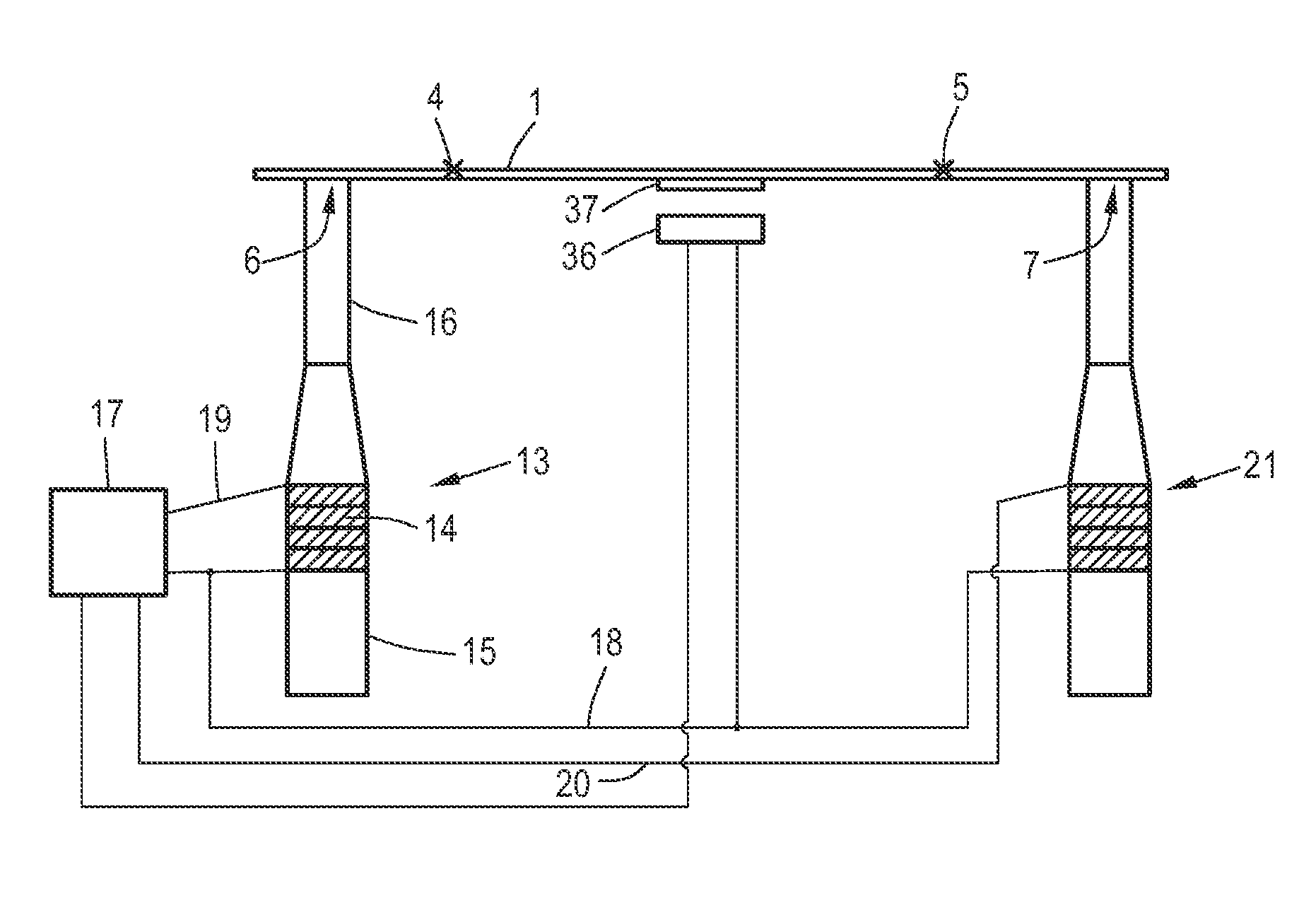
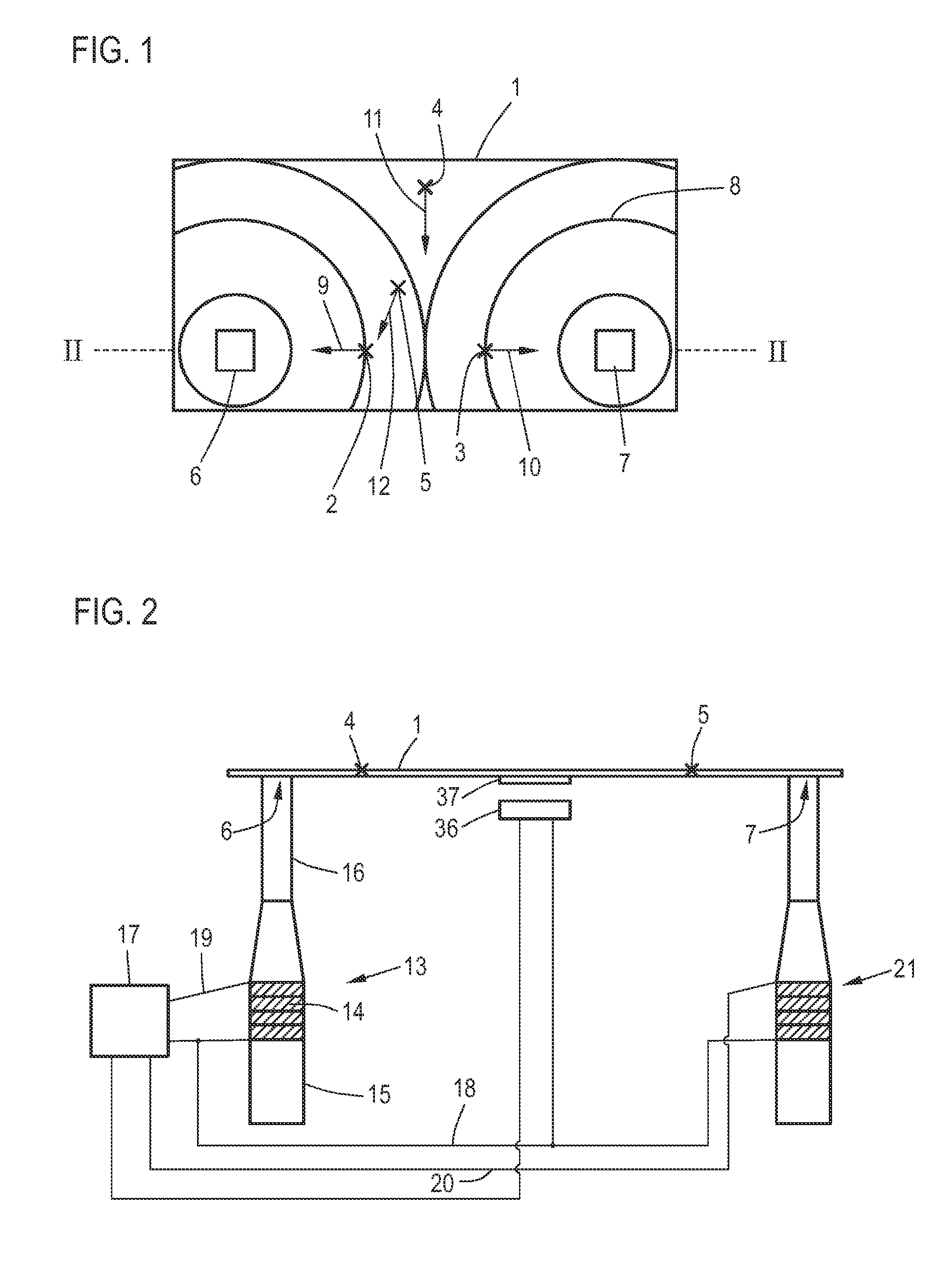
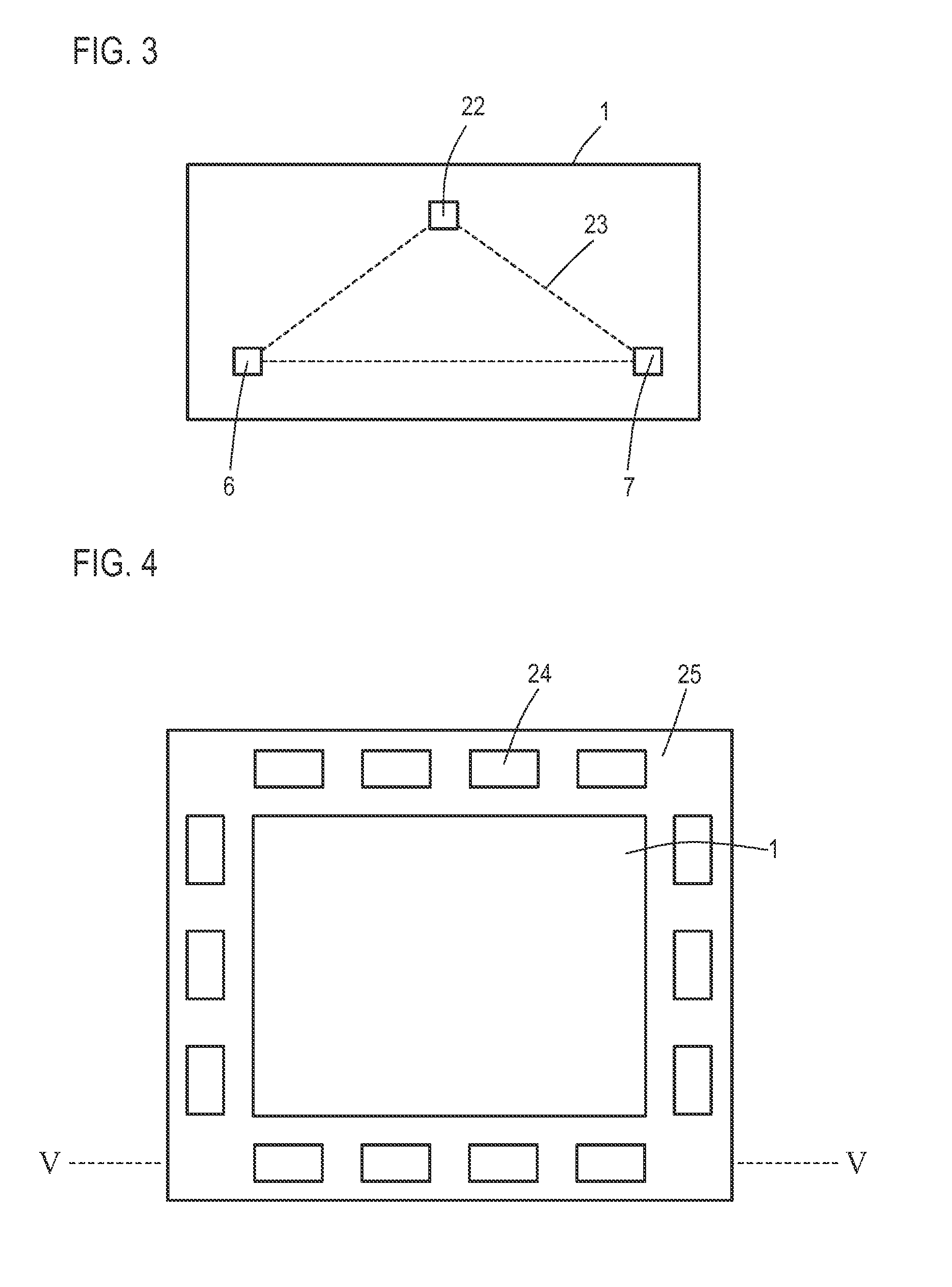
[0055]FIGS. 1-7 show numerous exemplary embodiments of oscillating conveyors according to the invention. Exemplary embodiments of the method according to the invention are described in the following as part of the explanations of the exemplary embodiments of the oscillating conveyors according to the invention. An explanation of an exemplary embodiment of a certain method in conjunction with a concrete exemplary embodiment of the oscillating conveyor does not limit the corresponding method to this specific type of oscillating conveyor.

[0056]FIG. 1 shows an exemplary embodiment of an oscillating conveyor for the two-dimensional movement of objects. First, on the basis of a plan view of the oscillating plate 1, the movement of the objects 2, 3, 4, and 5 on the oscillating plate 1 under excitation of the oscillating plate 1 at the excitation positions 6 and 7 will be described. The technical implementation of the excitation will be explained later in detail with reference to FIG. 2, wh...


PUM


Abstract

An oscillating conveyor for the two-dimensional movement of objects, comprising an oscillating plate, on the conveying surface of which at least one object is movable by the oscillations of the oscillating plate, and at least two excitation elements for exciting oscillations in the oscillating plate, wherein the excitation elements are ultrasound transducers coupled to the oscillating plate at excitation positions spaced a certain distance apart, by means of which transducers the oscillating plate can be excited to oscillate at the excitation position in question as a function of a control signal, which can be sent individually by a control unit to each excitation element.

Description

CROSS-REFERENCE TO RELATED APPLICATIONS[0001]The present application claims priority of 10 2014 111 168.0, filed Aug. 6, 2014, the priority of this application is hereby claimed and this application is incorporated herein by reference.BACKGROUND OF THE INVENTION[0002]The invention pertains to an oscillating conveyor for the two-dimensional movement of objects, comprising an oscillating plate, on the conveying surface of which at least one object can be moved by the oscillations of the oscillating plate, and at least two excitation elements for exciting oscillations of the oscillating plate.[0003]Oscillating conveyors are used to convey a large variety of objects, especially relatively small ones. The objects are conveyed by vibrations. Typically, rigid conveyor rails or rigid plates are used, which perform an elliptical movement and thus transport the objects by means of “micro-tosses”.[0004]During the transport or movement of objects such as electrical components, for example, it i...

Claims


Application Information

Patent Timeline
IPC IPC(8): G05D19/02B65G27/32
CPCG05D19/02B65G27/32B06B3/00B65G27/00B65G27/24B06B1/0611
Inventor BOTT, KLAUSMESAN, IZUDINMOJRZISCH, SEBASTIANTWIEFEL, JENSWALLASCHECK, JORG
Owner AFAG HLDG AG
Why Eureka
Try Eureka