Display module using blue-ray or ultraviolet-ray light sources

a technology of ultraviolet light and display module, which is applied in the direction of discharge tube/lamp details, discharge tube luminescnet screen, discharge tube/lamp details, etc., can solve the problems of insufficient transparent ito effect, high price of pdp, unstable performance, etc., and achieves less light loss, higher brightness, and more stable light sources

Inactive Publication Date: 2006-12-14
ARIMA OPTOELECTRONICS
View PDF1 Cites 6 Cited by
  • Summary
  • Abstract
  • Description
  • Claims
  • Application Information

AI Technical Summary

Benefits of technology

[0012] The primary objective of the present invention is to provide a display module using blue-ray or ultraviolet-ray light sources to directly excite RGB trichromatic colors, wherein a blue ray or an ultraviolet ray is used as the light sources of the backlight module in order to have more stable light sources; the blue ray or ultraviolet ray is used to excite the single-color fluorescent element on each grid in order to have a higher brightness and a less light loss.
[0013] Another objective of the present invention is to provide a display module using blue-ray or ultraviolet-ray light sources, wherein only one single-color fluorescent element is disposed inside one grid so that the cost can be reduced, in contrast with the conventional technologies that multiple fluorescent elements are disposed inside one grid.
[0014] Yet another objective of the present invention is to provide a display module using blue-ray or ultraviolet-ray light sources, which combines the advantages of LCD and PDP.

Problems solved by technology

However, PDP is very expensive and consumes too much power, and the effect of the transparent ITO is not well enough.
A voltage is used to create an isoionic effect to generate an ultraviolet ray, and the spectrum thereof is too wide; thus, the performance is unstable.
However, if LCD is compared with CRT by the price per inch of the panel, a LCD panel is much more expensive than a traditional CRT TV.

Method used


Image

  • Display module using blue-ray or ultraviolet-ray light sources
  • Display module using blue-ray or ultraviolet-ray light sources
  • Display module using blue-ray or ultraviolet-ray light sources

Examples


Embodiment Construction

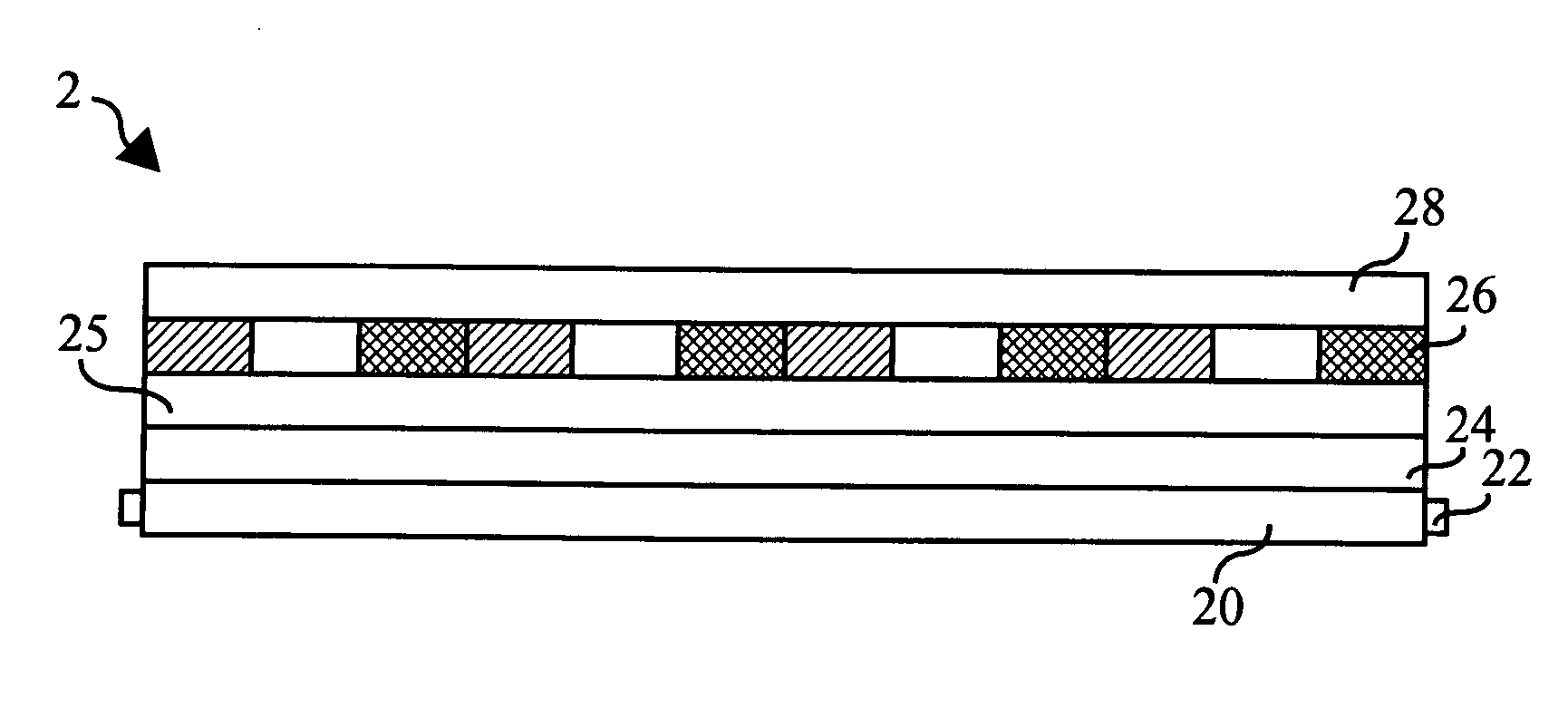
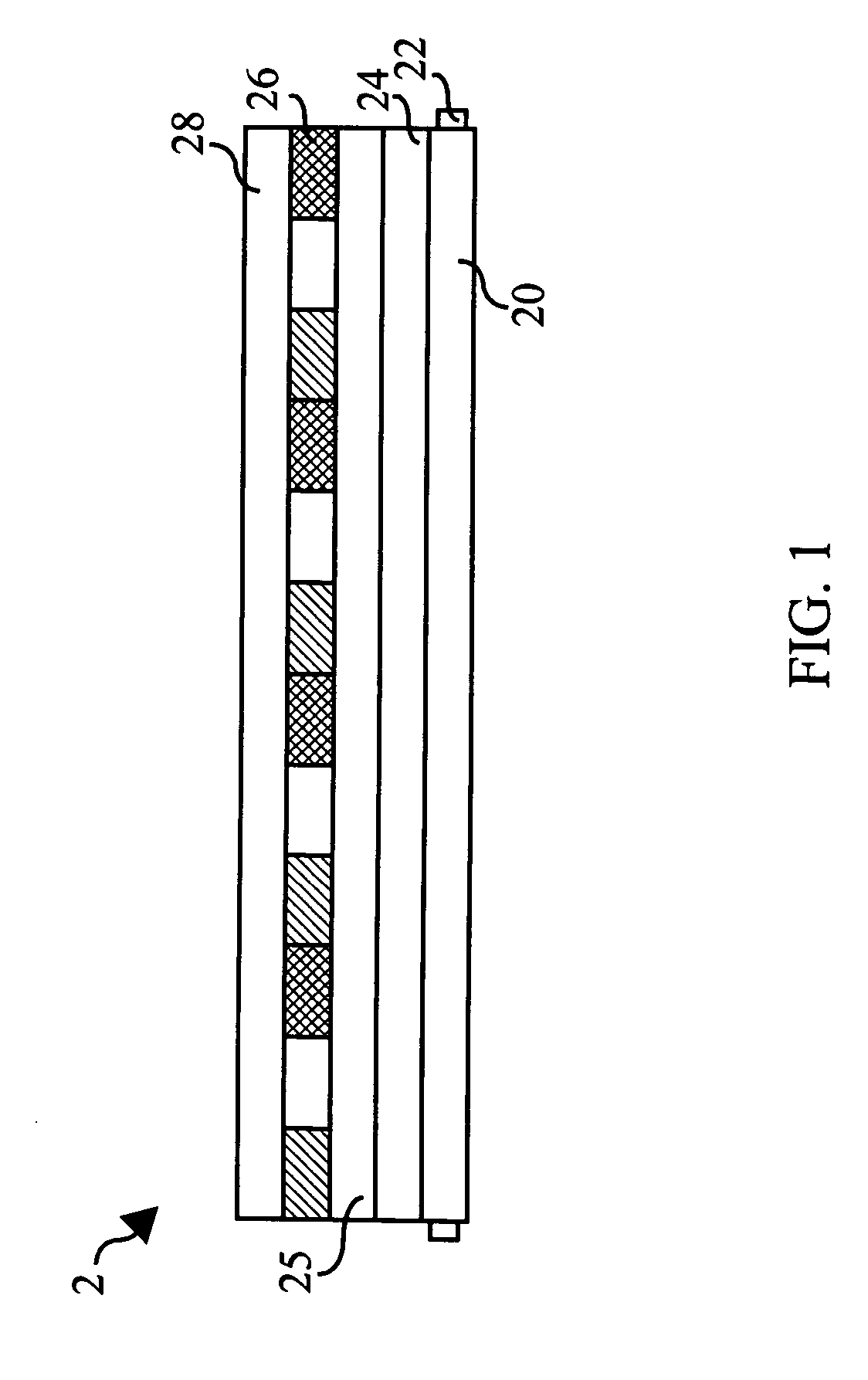
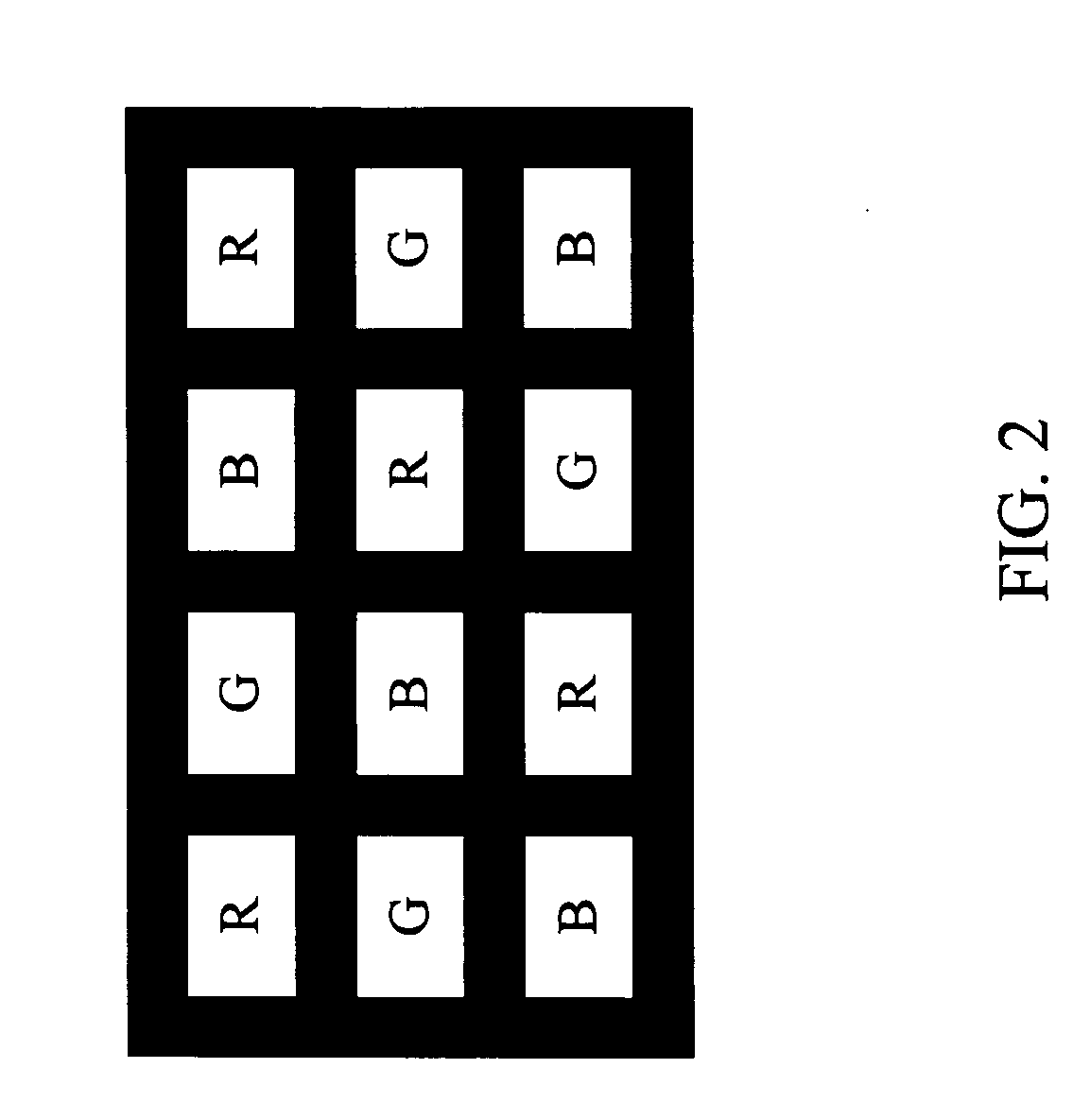
[0019] Refer to FIG. 1 a section view according to one aspect of the display module using blue-ray or ultraviolet-ray light sources of the present invention. The display module 2 using blue-ray or ultraviolet-ray light sources comprises a light guide plate 20, and multiple blue-ray or ultraviolet-ray light sources 22 are installed on the light guide plate 20. The light sources 22 are used to emit a short-wavelength light with the wavelength ranging from 300 to 460 nm. A diffuser plate 24 is installed on the light guide plate 20; a liquid crystal layer 25 and an excited layer 26 are further installed on the diffuser plate 24. The excited layer 26 has multiple grids, and fluorescent elements of the trichromatic colors red (R), green (G), and blue (B) are disposed on those grids, and each grid has only one single-color fluorescent element. The short-wavelength light is guided by the light guide plate 20 to the diffuser plate 24, and then, the short-wavelength light is diffused by the d...


PUM

PropertyMeasurementUnit
wavelengthaaaaaaaaaa
pressureaaaaaaaaaa
wavelengthaaaaaaaaaa

Abstract

The present invention discloses a display module using blue-ray or ultraviolet-ray light sources to excite RGB fluorescent powders to emit light, which comprises a light guide plate, at least one blue-ray or ultraviolet-ray light source, a diffuser plate, a liquid crystal layer and a fluorescent-powder excited layer. The blue-ray or ultraviolet-ray light sources emit a short-wavelength light with the wavelength ranging from 360 to 460 nm; the light guide plate will guide the short-wavelength light to the diffuser plate; the diffuser plate will further diffuse the short-wavelength light; the diffused short-wavelength light will pass through the liquid crystal layer and reach the fluorescent-powder excited layer where the short-wavelength light excites the fluorescent powder to emit light. The excited layer has multiple grids where RGB fluorescent elements are disposed, and each grid has only one single-color fluorescent element. The liquid crystal layer can determine whether the short-wavelength light diffused by the diffuser plate is allowed to pass through a specified grid to excite the fluorescent element to emit light. The present invention combines the advantages of low voltage as in LCD and high brightness as in self-lighting PDP, and the present invention has the benefits of higher brightness, less light loss, and reduced cost.

Description

BACKGROUND OF THE INVENTION [0001] 1. Field of the Invention [0002] The present invention relates to a display module using blue-ray or ultraviolet-ray light sources, particularly to a display module using blue-ray or ultraviolet-ray light sources to excite RGB fluorescent powders to emit light. [0003] 2. Description of the Related Art [0004] In a Liquid Crystal Display (LCD) panel, a backlight module in the rear side emits light, and the light is uniformly spread to the front side via the backlight module and an assemblage of prisms; the liquid crystal molecules will align according to received image signals, which can determine whether the light to pass through or not. [0005] The backlight module is one of the key components of LCD panel. As liquid crystal itself does not emit light, sufficient brightness and uniformly distributed light source, which enables the LCD panel to present pictures, is provided by a backlight module. [0006] LCD panel has been universally used in monitors...

Claims


Application Information

Patent Timeline
Patent Type & Authority Applications(United States)
IPC IPC(8): G02F1/1335
CPCG02F1/133617
Inventor HSU, CHIH MINGLEE, YUH WEN
Owner ARIMA OPTOELECTRONICS
Why Eureka
Try Eureka