Endoscope and endoscopic system

Inactive Publication Date: 2006-12-21
OLYMPUS CORP
View PDF7 Cites 16 Cited by
  • Summary
  • Abstract
  • Description
  • Claims
  • Application Information

AI Technical Summary

Benefits of technology

[0018] The present invention has been made in view of the above-mentioned problems and it is therefore an object to provide an endoscope with which a

Problems solved by technology

In the endoscope described in the above-mentioned publication, if the surgeon grasps the grasping section with a right hand, the operation is extremely difficult.
For this reason, in this endoscope, if the arrangement positions of the bending operation knob, the suction button, and the air water button are not changed for the surgeon who grasps the endoscope with the right hand, there is a problem in that satisfactory operability cannot be ensured.
In this manner, some endoscopes have a problem in that operability is degraded depending on the left and or the right hand of the surgeon for grasping the grasping section.
In the endoscope of the previous cases, the endoscope of this type may degrade the operability due to the existence of the universal c

Method used


Image

  • Endoscope and endoscopic system
  • Endoscope and endoscopic system
  • Endoscope and endoscopic system

Examples


first embodiment

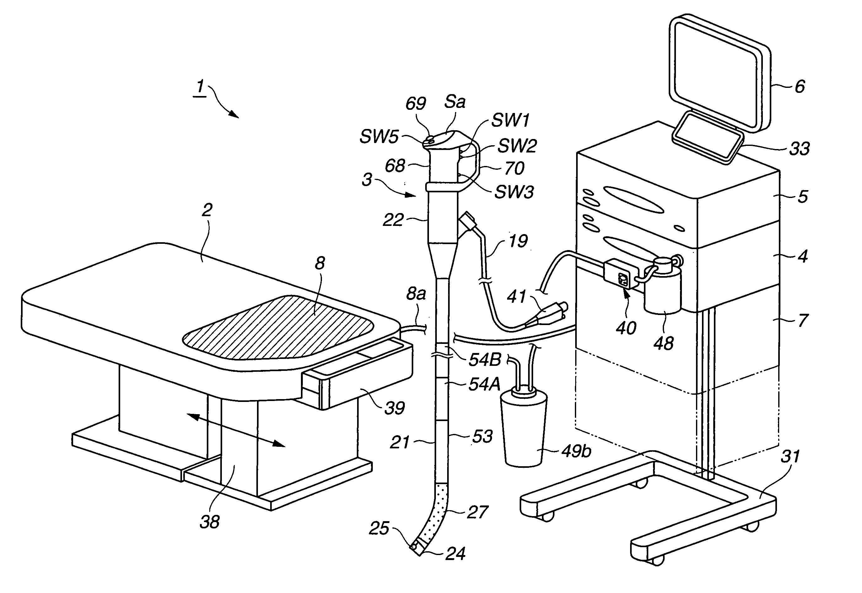
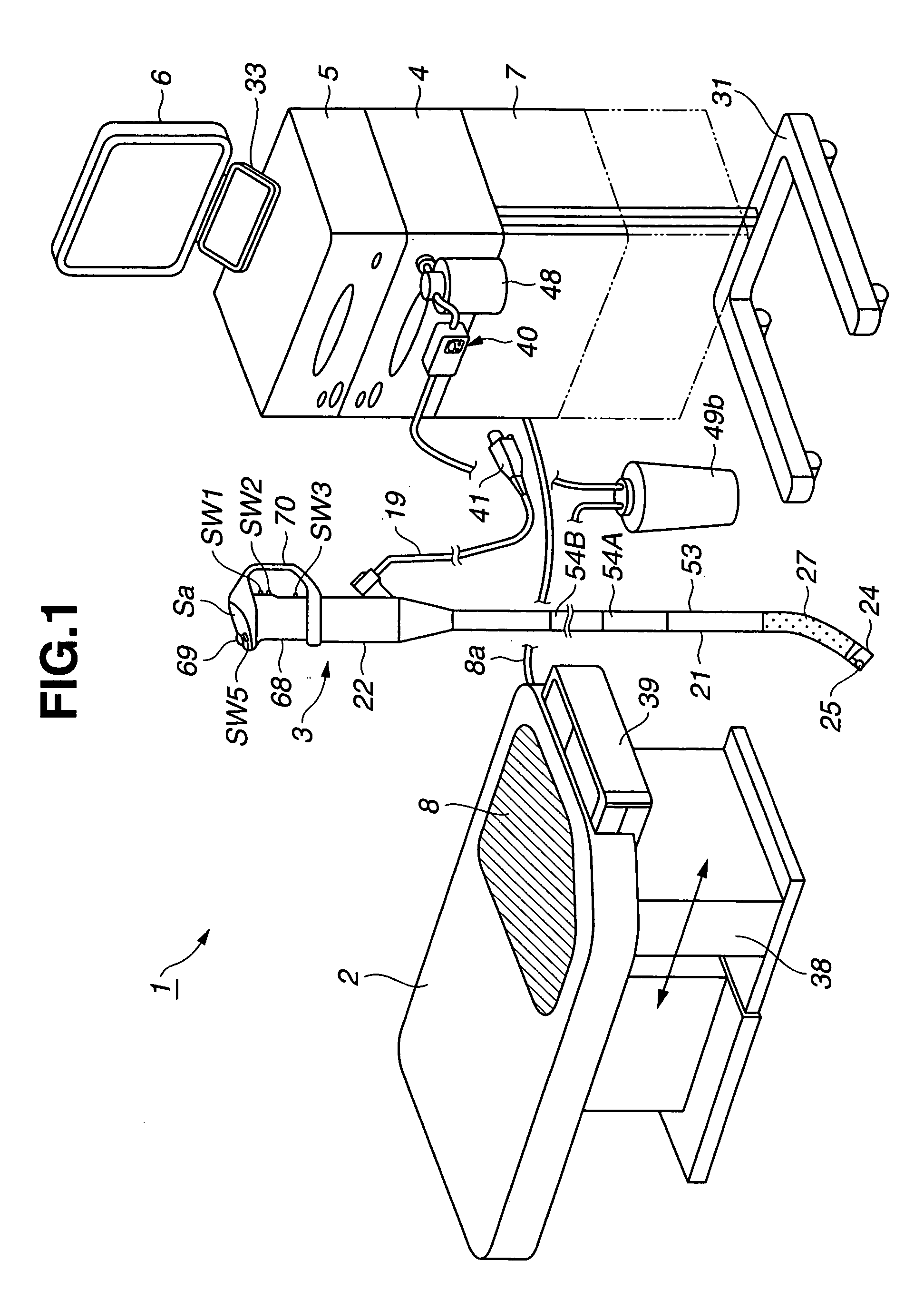
[0071] Before a specific structure of an endoscopic system according to the present invention will be described, a description is first given of a schematic structure of the endoscopic system with reference to FIGS. 1 to 3.

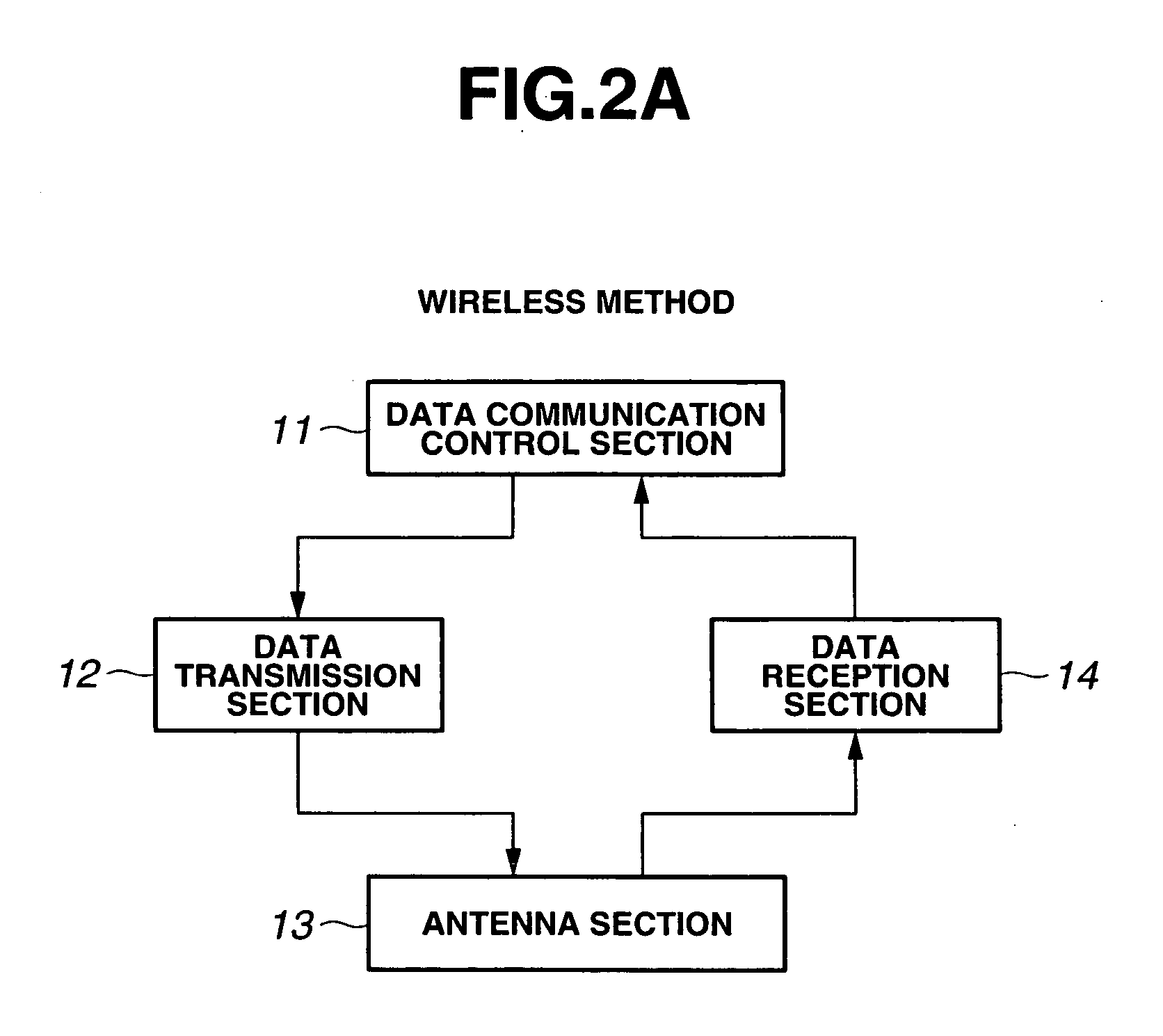
[0072]FIG. 1 shows a schematic structure of an endoscopic system according to the first embodiment of the present invention, FIGS. 2A to 2C are block diagrams showing each example of data communication mode in the endoscopic system according to the first embodiment, and FIG. 3 is a perspective view showing a specific outer appearance shape of an AWS unit peripheral section in the endoscopic system according to the first embodiment.

[0073] As shown in FIG. 1, an endoscopic system 1 includes a flexible endoscope (also referred to as scope) 3 for performing an endoscopic inspection by inserting the endoscope in a body cavity of a patient (not shown) lying on an inspection bed 2. The endoscopic system 1 includes an air water supply / suction unit having functions of air...

second embodiment

[0184] Next, the endoscopic system according to the present invention will be described.

[0185]FIGS. 14A to 14E show a specific outer appearance shape or the like of the endoscope in the endoscopic system according to the second embodiment of the present invention.

[0186] It should be noted that FIG. 14A shows a state partially cut off from the side in the vicinity of the operation section, FIG. 14B is a front view as seen from the right hand side of FIG. 14A, FIG. 14C is a plan view as seen from the top of FIG. 14A, and FIG. 14D shows a part of the endoscope 3F as a modified example.

[0187] In the endoscope 3B according to the second embodiment, in the endoscope 3 of the first embodiment, an transmission and reception antenna section 121 built in the operation section 22 is used instead of providing the signal transmission signal line 73b.

[0188] Information such as image data captured by the CCD 25 or operation data in the case of operating the track ball 69 or the like as the oper...


PUM


Abstract

An endoscope of the present invention includes an insert section inserted in a subject body, an operation section provided on a base end side of the insert section, a grasping section provided to the operation section and formed to be substantially bilaterally symmetric to a reference line extending in a longitudinal direction, and a plurality of instruction input sections provided to be substantially bilaterally symmetric to the reference line extending in the longitudinal direction of the grasping section.

Description

CROSS REFERENCES TO RELATED APPLICATIONS [0001] This application is a continuation application of PCT / JP2005 / 003326 filed on Feb. 28, 2005 and claims benefit of Japanese Applications No. 2004-054675 filed in Japan on Feb. 27, 2004 and No. 2004-054676 filed in Japan on Feb. 27, 2004, the entire contents of each of which are incorporated herein by their reference.BACKGROUND OF THE INVENTION [0002] 1. Field of the Invention [0003] The present invention relates to an endoscope to be inserted in a body cavity or the like for performing an endoscopy or the like and an endoscopic system having the endoscope. [0004] 2. Description of the Related Art [0005] In recent years, endoscopes having an illumination section and an observation section at a distal end of an elongated insert section are being widely adopted in a medical field and an industrial field. [0006] For example, an endoscope is known which has a flexible insert section and a bending section in the vicinity of a distal end of the...

Claims


Application Information

Patent Timeline
IPC IPC(8): A61B1/00A61B1/005A61B1/015A61B1/05A61B5/06G02B23/24
CPCA61B1/00016A61B1/00039A61B1/0051A61B1/0052A61B1/0053A61B1/00128A61B1/05A61B5/06A61B5/704A61B2560/0437G02B23/2476A61B1/015A61B5/062A61B1/00042
Inventor ONODA, FUMIYUKIUCHIMURA, SUMIHIRONOGUCHI, TOSHIAKISUZUKI, KATSUYA
Owner OLYMPUS CORP
Why Eureka
Try Eureka