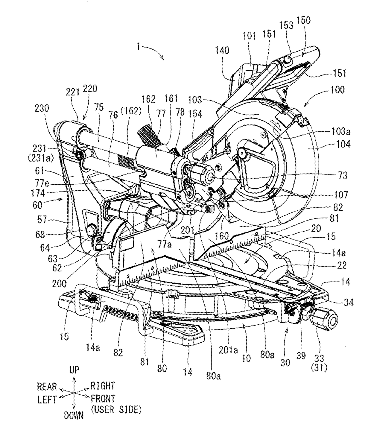
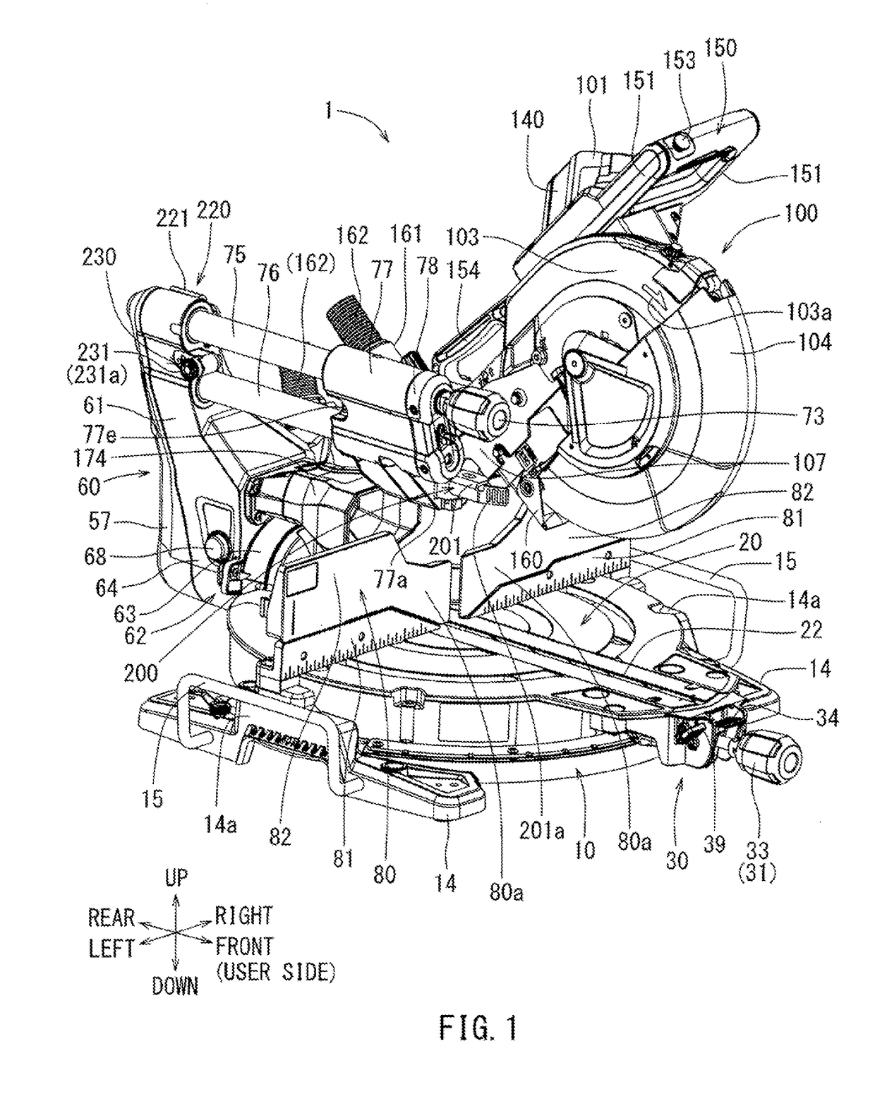
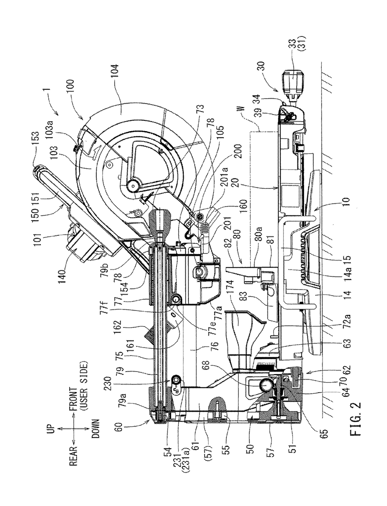
Cutting device

a cutting device and tabletop technology, applied in the field of tabletop cutting devices, can solve the problems of affecting user operation comfort, large transmission loss of operation force, and impaired operability in this respect, and achieve the effect of improving the operability of the tabletop cutting device and lowering the height of the upper surface of the tabl

Active Publication Date: 2018-05-17
MAKITA CORP
View PDF2 Cites 4 Cited by
  • Summary
  • Abstract
  • Description
  • Claims
  • Application Information

AI Technical Summary

Benefits of technology

[0019]According to such an embodiment, the operation member of the first rotation lock mechanism and the operation member of the second rotation lock mechanism are vertically disposed, and also operability of the operation members is secured. Furthermore, the transmission rod and the lock member of the first rotation lock mechanism, which are members of the engagement side with respect to the base, are arranged

Problems solved by technology

Because of this user's preference, the configuration in which the rotation position of the table is locked by applying the spring force (patent document 4) has been producing a problem of impairing user's operation comfort.
Furthermore, in the configuration in which the rotation position of the

Method used


Image

  • Cutting device
  • Cutting device
  • Cutting device

Examples


Embodiment Construction

[0061]The detailed description set forth below, when considered with the appended drawings, is intended to be a description of exemplary embodiments of the present invention and is not intended to be restrictive and / or to represent the only embodiments in which the present invention can be practiced. The term “exemplary” used throughout this description means “serving as an example, instance, or illustration,” and should not necessarily be construed as preferred or advantageous over other exemplary embodiments. The detailed description includes specific details for the purpose of providing a thorough understanding of the exemplary embodiments of the invention. It will be apparent to those skilled in the art that the exemplary embodiments of the invention may be practiced without these specific details. In some instances, these specific details refer to well-known structures, components and / or devices that are shown in block diagram form in order to avoid obscuring significant aspect...


PUM

PropertyMeasurementUnit
Angleaaaaaaaaaa
Lengthaaaaaaaaaa
Forceaaaaaaaaaa

Abstract

The first rotation lock mechanism 31 is configured such that a screw force produced by a rotation operation of an operation member 33 is transmitted to a lock member 42 via a transmission bracket 36 and a transmission rod 40. Through minimizing the length of the screw shaft 35, the transmission bracket 36, and the transmission rod 40, the position of a lock member which a screw shaft 35 is brought into contact with and the screw force is directly applied to is arranged to be closer to a user in comparison with conventional prior art. As a result, transmission loss of the screw force can be reduced, enhancing accuracy and consistency for the fixing force with respect to the table can be improved.

Description

CROSS-REFERENCE[0001]This application claims priority to Japanese patent application serial number 2016-220813, filed on Nov. 11, 2016, the contents of which are incorporated herein by reference in their entirety.TECHNICAL FIELD[0002]The present invention generally relates to a tabletop cutting device, which is referred to as a sliding circular saw and / or a tabletop circular saw, used for cutting a material to be cut (workpiece), such as mainly a wooden material.BACKGROUND ART[0003]These types of tabletop cutting devices include a table on which the material to be cut (workpiece) is placed and a cutting device main body that is supported on a rear part of the table so as to be movable along an up-to-down direction. The cutting device main body includes a circular cutting blade (cutting edge) that can be rotated by an electric motor as a driving source. Cutting work can be performed by moving the cutting main body in a downward direction, causing the rotating cutting blade to cut the...

Claims


Application Information

Patent Timeline
IPC IPC(8): B23D47/02B23D45/04
CPCB23D47/025B23D45/048B27C5/02B23D47/126B27B5/29
Inventor YAMAMURA, GOH
Owner MAKITA CORP
Why Eureka
Try Eureka