

Racket and method of stringing the racket
a racket and stringing technology, applied in the field of rackets, can solve the problems of inadequate stringing pattern design and stringing of rackets, relative little effort devoted to string positioning, and ineffective stringing design of rackets
- Summary
- Abstract
- Description
- Claims
- Application Information
AI Technical Summary
Problems solved by technology
Method used
Image

Examples
first embodiment
[0059] V. FIG. 7
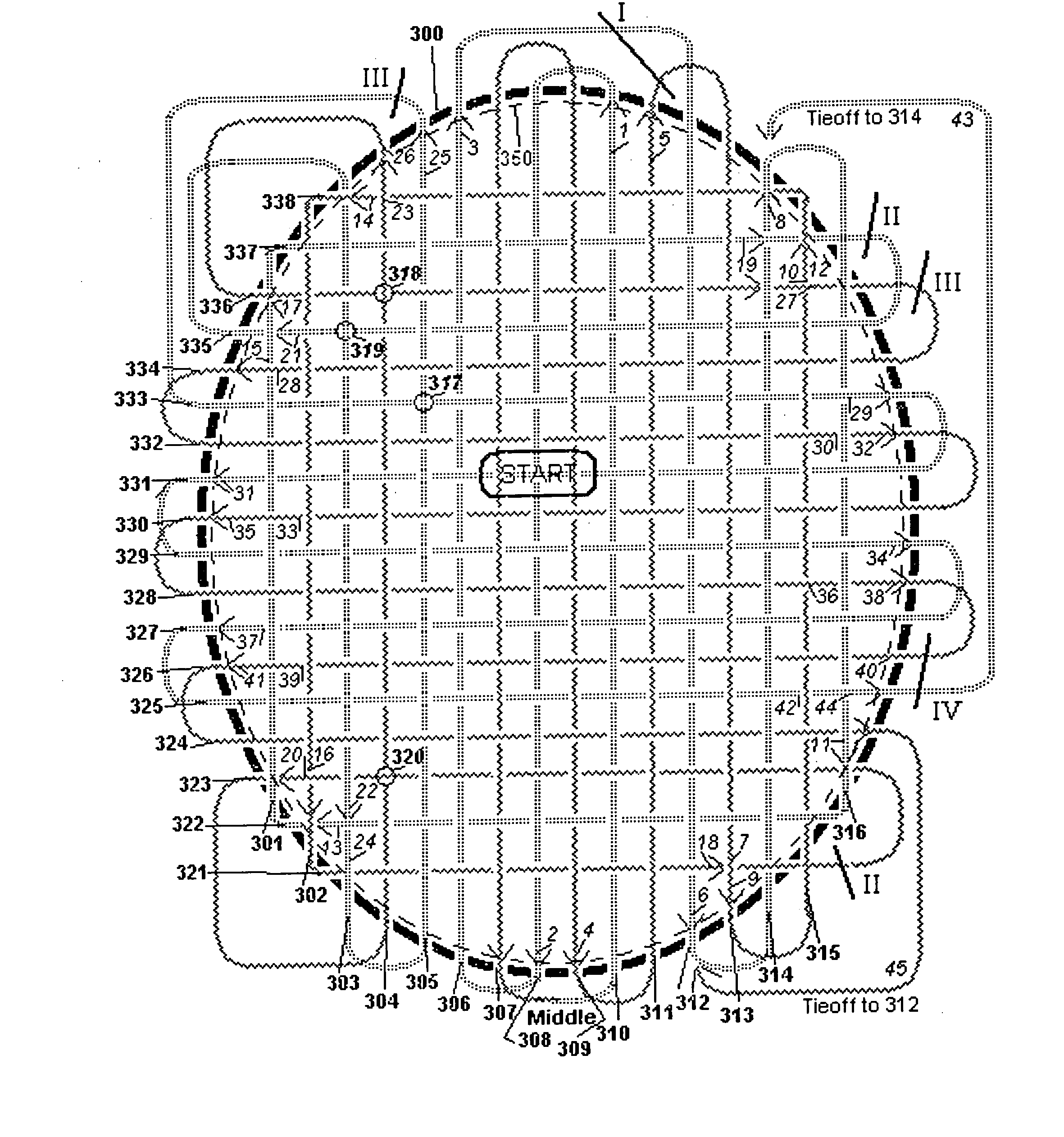
[0060] Referring now to FIG. 7, a first exemplary embodiment of a stringing technique conducted for a first type of racket geometry (e.g., WILSON® PROSTAFF® 6.0 and / or WILSON® TRIAD® 6.0 racket frames) is illustrated. As shown, cross strings 321-338 are numbered along the left side of a frame 300 while main strings 301-316 are numbered at the bottom of frame 300. Two string representations (solid and zigzag) have been used in the stringing diagrams to help clarify the different “halves” of the string, although the strings described below are segments of a continuous string between two tie-offs onto main strings 312 and 314.
[0061] In using this pattern, the rackets were strung with a concerted effort to make the racket utilize alternating strings to the extent possible. Most rackets of current design have six main string grommets in the throat, making a fully alternating pattern impossible for the main strings. But alternating strings are less important for the longe...
second embodiment
[0088] VI. FIG. 8
[0089] Referring to FIG. 8, a second exemplary embodiment of a racket stringing technique is illustrated. As previously labeled, and similarly further applicable to FIGS. 9-16 as well, cross strings 421-438 are numbered on the left side and main strings 401-416 are numbered below. This pattern reduces the exposure of the more central strings to crossing of neighbors (retaining an interference between main string 403 and cross string 436 at location 417), and has a fairly full alternating pattern between cross strings 422 and 437 and main strings 403 through 414, excepting the six (6) central strings of string bed 450. String bed 450 commences with a polygon-shaped (e.g., rectangular) loop that goes from (starting from upper right) cross string 438, down main string 402, across on cross string 421, then back up to main string 416.
[0090] Such stringing may begin with a “loop” about the outer strings according to the pattern describe above, but it is contemplated that...
third embodiment
[0092] VII. FIG. 9
[0093] Referring to FIG. 9, a third exemplary embodiment of a racket stringing technique similar to FIG. 7 or 8 with an additional stringing feature is illustrated. An initial loop is positioned between the outermost main strings and the second-from-outermost cross strings. Keeping strings that intersect substantially near frame 500 in this pattern, are desirable to keep the “heart” of the string bed 550 optimally pliant.
[0094] In a subsequent secondary implementation, small holes were drilled in frame 500 to allow tie-offs to main string 501 (from “final cross strings 521 and 523). On both of the existing frames, the grommets for main string 501 are too small to allow other strings to pass through them to tie-off there, and creating the additional drilled holes allows such a tie-off.
PUM
 Abstract
Description
Claims
Application Information