X-ray diffraction apparatus

Inactive Publication Date: 2007-01-04
RIGAKU CORP
View PDF6 Cites 19 Cited by
  • Summary
  • Abstract
  • Description
  • Claims
  • Application Information

AI Technical Summary

Benefits of technology

This patent describes an x-ray machine that allows multiple types of X-rays to hit a sample simultaneously, making it possible to measure them all at once through X-ray diffusion measurements.

Problems solved by technology

This patent describes an X-ray diffraction apparatus that uses multiple types of X-rays to measure samples. However, there may be limitations in measuring simultaneously using all of these X- rays without interfering with each other. Therefore, this technical problem addressed by this patent is finding ways to separate or reduce the influence of different X-rays during measurements to improve accuracy and sensitivity.

Method used


Image

  • X-ray diffraction apparatus
  • X-ray diffraction apparatus
  • X-ray diffraction apparatus

Examples


Embodiment Construction

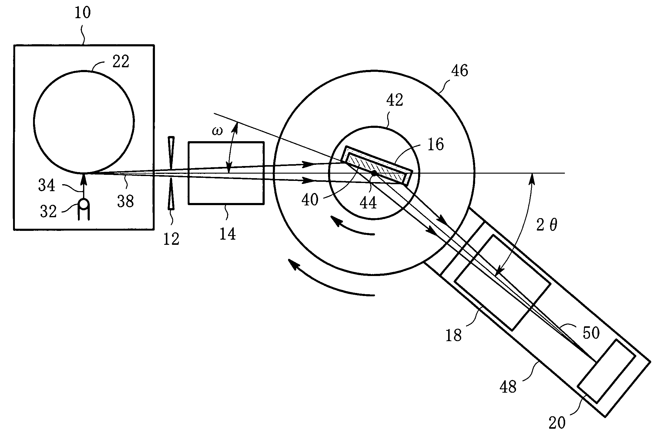
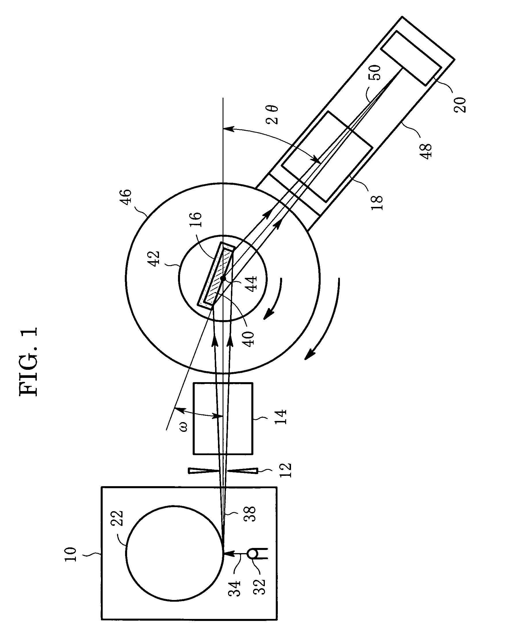
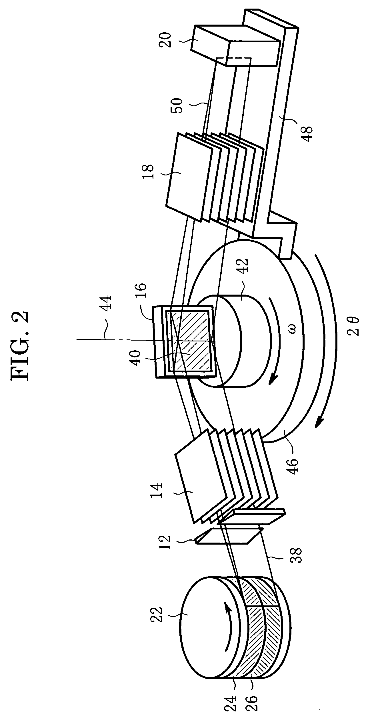
[0020] Embodiments of the present invention will now be described in detail below with reference to the drawings. FIG. 1 is a plan view of one embodiment of an X-ray diffraction apparatus according to the present invention, and FIG. 2 is a perspective view of the embodiment, noting that FIG. 2 shows only an anode for an X-ray tube. Referring to FIGS. 1 and 2, the X-ray diffraction apparatus has an X-ray tube 10, a divergence slit 12, an incident-side Soller slit 14, a sample holder 16, a receiving-side Soller slit 18 and an X-ray detector 20.

[0021] The X-ray tube 10 is a rotating-anode X-ray tube and its rotating anode 22 has, as shown in FIG. 3, the first target region 24 and the second target region 26. The first target region 24 is made of Co (cobalt), which is the first material, and has a ring shape. The second target region 26 is made of Cu (copper), which is the second material, and has a ring shape similarly. The two target regions 24 and 26 are sectioned in a direction par...


PUM


Abstract

An X-ray diffraction apparatus allows plural kinds of characteristic X-rays to be incident on a sample at the same time and thus allows X-ray diffraction measurement with the plural kinds of characteristic X-rays to be carried out at the same time. An X-ray tube includes an anode which has the first target region made of Co and the second target region made of Cu. The first and second target regions are sectioned in a direction (Z-direction) perpendicular to an X-ray take-off direction. Incident-side and receiving-side Z-direction-divergence restriction devices restrict the X-ray divergence in the Z-direction. An X-ray detector is position sensitive at least in the Z-direction and can detect separately a diffracted X-ray coming from the first sample region which is irradiated with the Co characteristic X-ray and another diffracted X-ray coming from the second sample region which is irradiated with the Cu characteristic X-ray. The detector may be a two-dimensional CCD sensor capable of executing a TDI operation.

Description


Claims


Application Information

Patent Timeline
Owner RIGAKU CORP
Why Eureka
Try Eureka