

Core Biopsy Device
a biopsy device and core technology, applied in the field of biopsy needles, can solve the problem of not providing a rotating cannula, and achieve the effect of maximizing the quantity of specimens
- Summary
- Abstract
- Description
- Claims
- Application Information
AI Technical Summary
Benefits of technology
Problems solved by technology
Method used
Image

Examples
Embodiment Construction
[0020] In the following detailed description of the preferred embodiments, reference is made to the accompanying drawings, which form a part hereof, and within which are shown by way of illustration specific embodiments by which the invention may be practiced. It is to be understood that other embodiments may be utilized and structural changes may be made without departing from the scope of the invention.
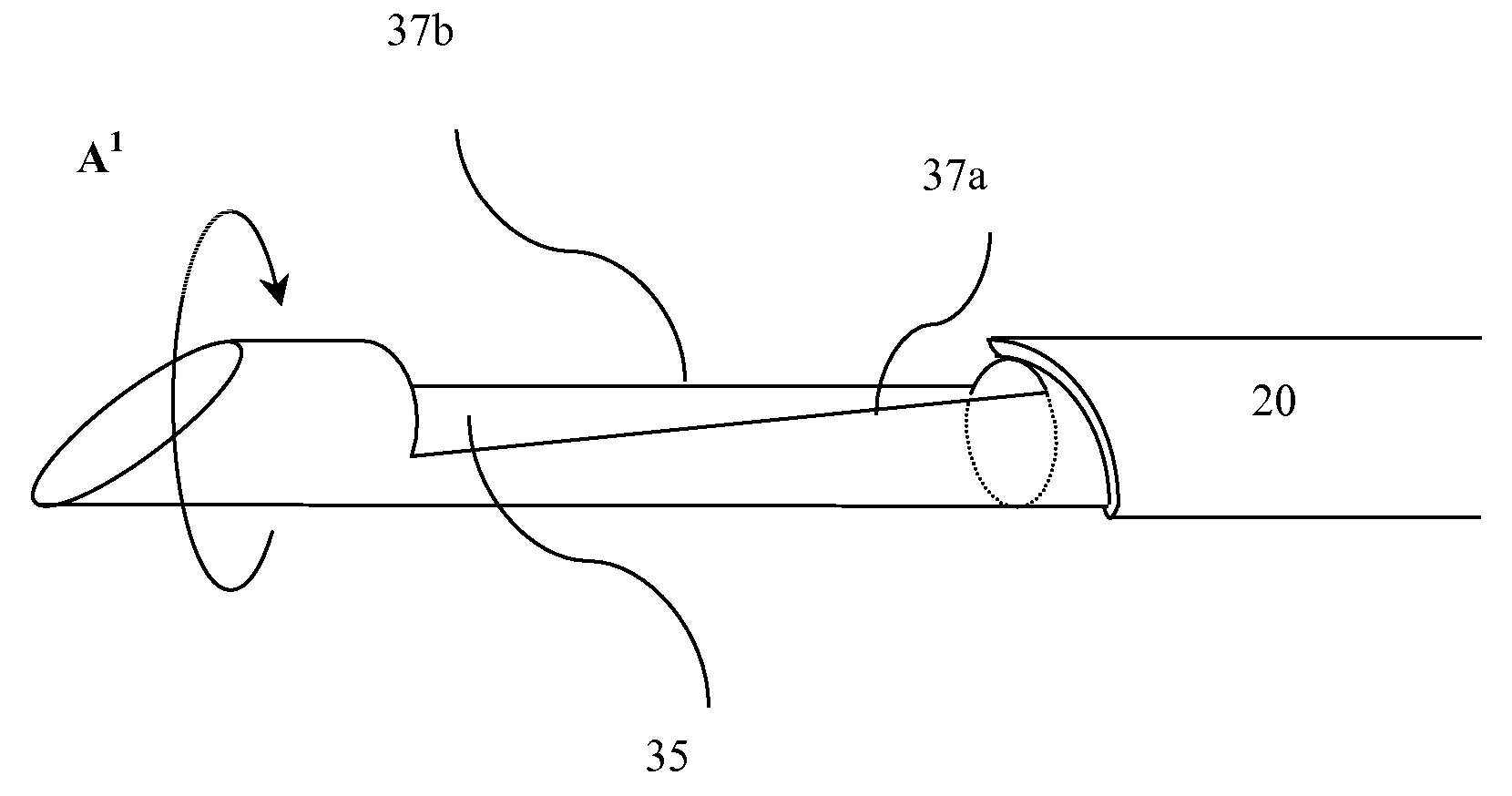
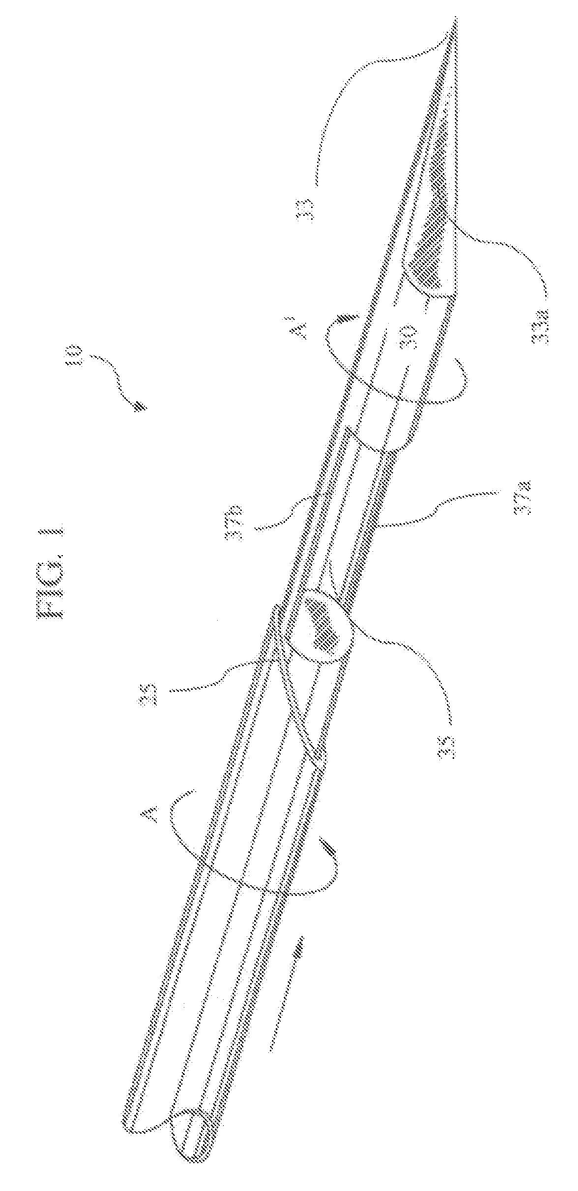
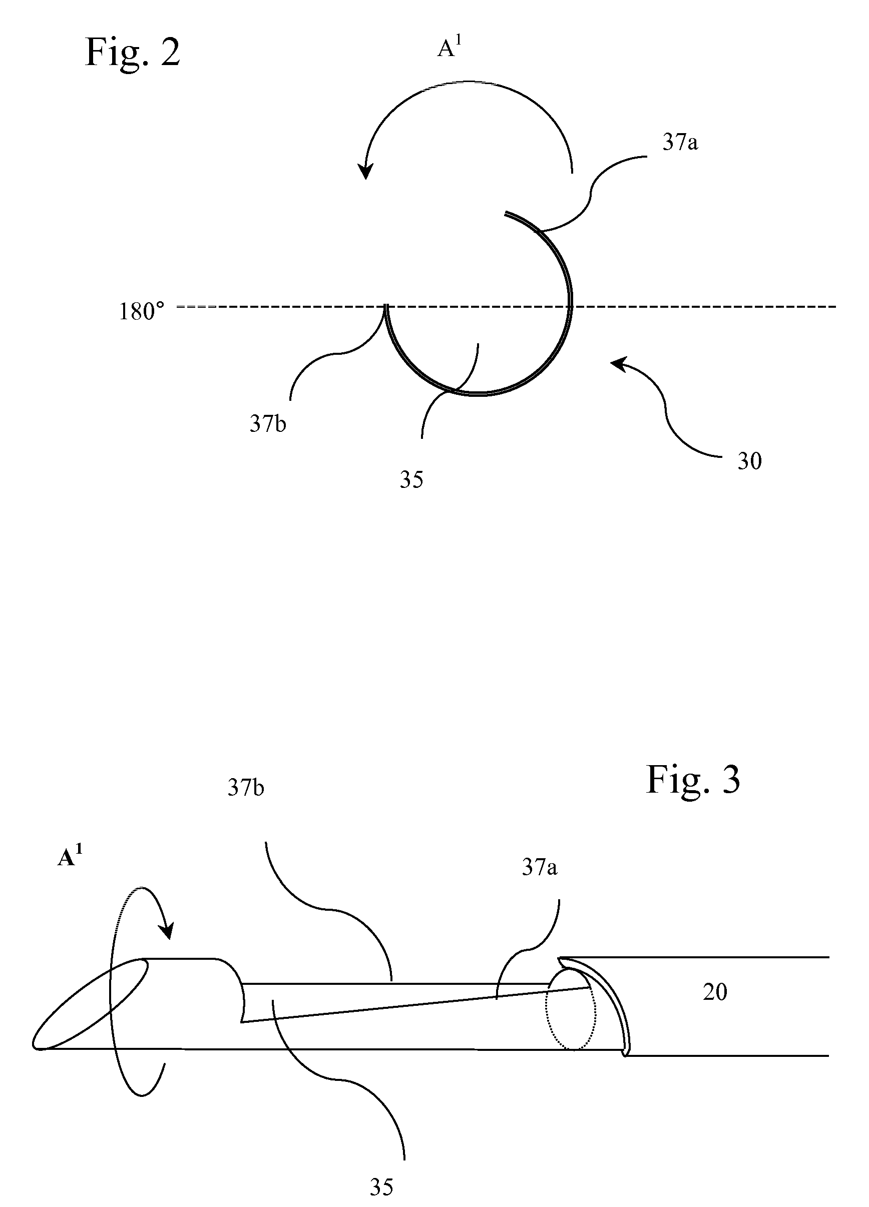
[0021] Referring now to FIG. 1, a preferred embodiment of the invention is shown illustrating the component parts of the novel biopsy device 10 in accordance with the present invention. As shown in FIG. 1, biopsy device 10 includes tubular outer cannula 20 which carries solid circular stylet 30. Outer cannula 20 is circular in cross-section, has an axis and circular passageway there through. Outer cannula 20 and stylet 30 are coaxial when assembled and have a common axis. Outer cannula 20 is equipped with distal portion 23 which is preferably tapered. The end of outer cannula 20 pr...
PUM
 Abstract
Description
Claims
Application Information