Wind turbine rotor blade with in-plane sweep and devices using same, and methods for making same

a technology of wind turbine rotor blade and in-plane sweep, which is applied in the field of blades, can solve problems such as overwhelming baseline aerodynamic pitching moments, and achieve the effects of reducing load, reducing or minimizing the amount of blade material needed, and maximizing twisting

Active Publication Date: 2008-03-18
GENERAL ELECTRIC CO
View PDF19 Cites 80 Cited by
  • Summary
  • Abstract
  • Description
  • Claims
  • Application Information

AI Technical Summary

Benefits of technology

[0008]In yet other aspects, the present invention provides a method for making a blade for a wind turbine. The method includes determining a blade shape by selecting sweep angles for elements of said blade so as to (a) increase or maximize an amount of twist induced and the distribution of the twist in such a manner as to create a reduction loads, (b) reduce or minimize an increase in blade material necessary to maintain tip deflection, (c) reduce or minimize negative effects on aerodynamics, and (d) maintain structural integrity, and fabricating a blade in accordance with the determined blade shape.
[0009]It will be appreciated that, when rotor blades are swept forward by the proper amount, configurations of the present invention reduce or eliminate a pitching moment at blade roots resulting from sweep. Also, a forward sweep of inboard sections of the rotor blades will not produce a harmful twist of measurable magnitude in those sections because the blade root is torsionally extremely rigid. Because the sweep of outboard sections of the blade remains unchanged relative to sections further inboard in configurations of the present invention, the twist induced by the outboard sweep also remains unchanged.
[0010]It will also observed that configurations of the invention present invention produce beneficial coupling between a flapwise (that is, out-of-plane) deflection of a rotor blade and twisting (that is, pitching) of the rotor blade with little or no increase in root pitch torque. Coupled twisting of the rotor blade also produces a general reduction in transient loads experienced by the wind turbine. Forward sweep inboard also enables greater sweep-induced coupling magnitude for a blade geometry that will fit within a given geometric envelope.

Problems solved by technology

However, if the root of the blade remains unswept or is swept aft, the pitching moment induced over the entire blade is reacted at the root of the blade through pitch drive hardware.
For even modest sweep, this moment can overwhelm baseline aerodynamic pitching moments for which the pitch hardware is designed.

Method used


Image

  • Wind turbine rotor blade with in-plane sweep and devices using same, and methods for making same
  • Wind turbine rotor blade with in-plane sweep and devices using same, and methods for making same
  • Wind turbine rotor blade with in-plane sweep and devices using same, and methods for making same

Examples


Embodiment Construction

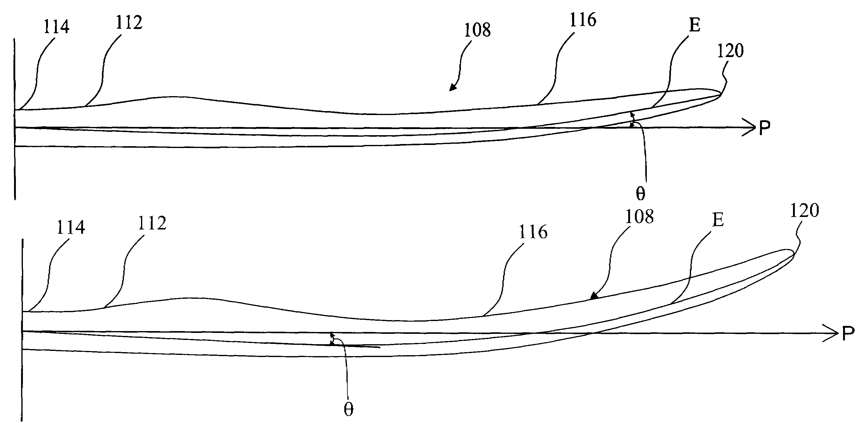
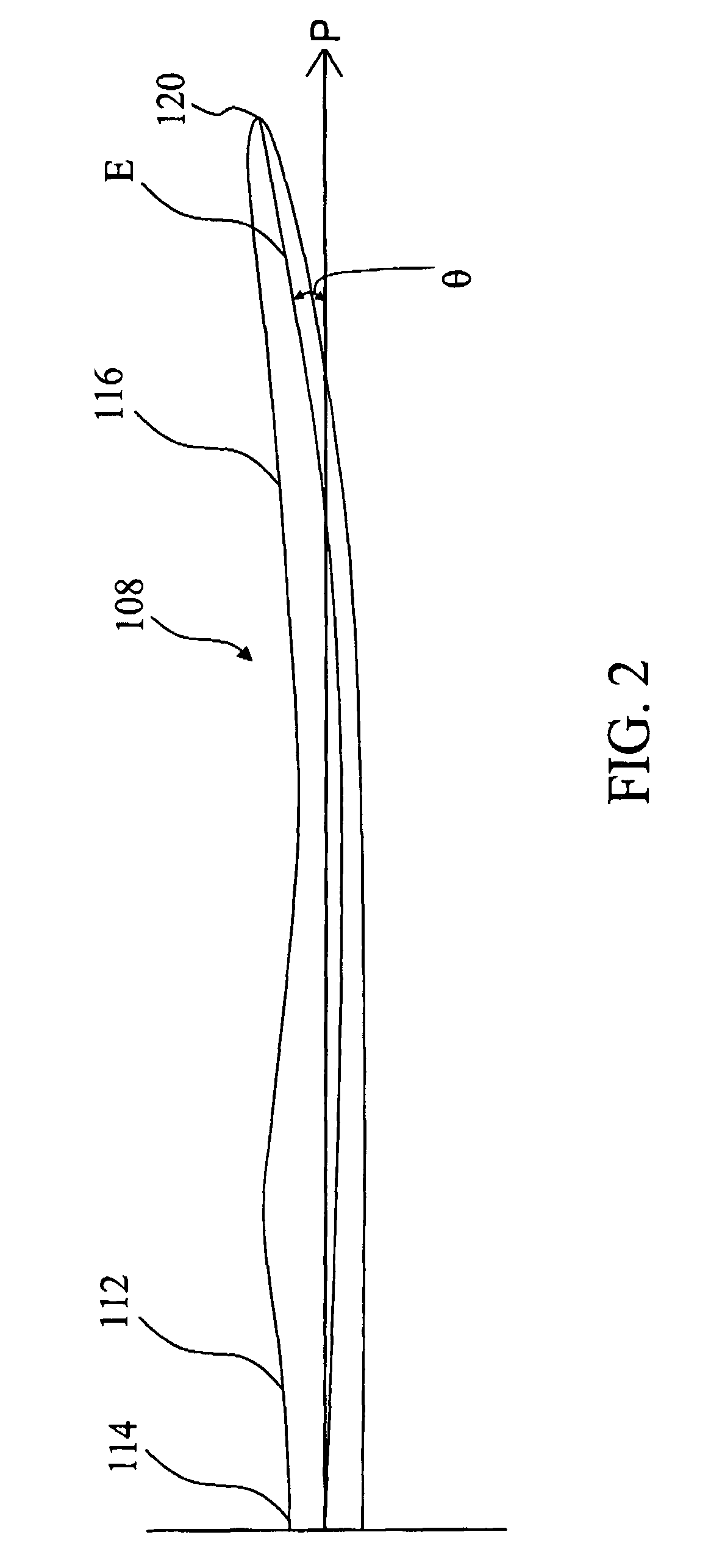
[0017]As used herein, the term “sweep” refers to an angle of an elastic axis relative to a pitch axis of a blade, where the “elastic axis” refers to a locus of points defining a torsional center at each spanwise section of the blade.

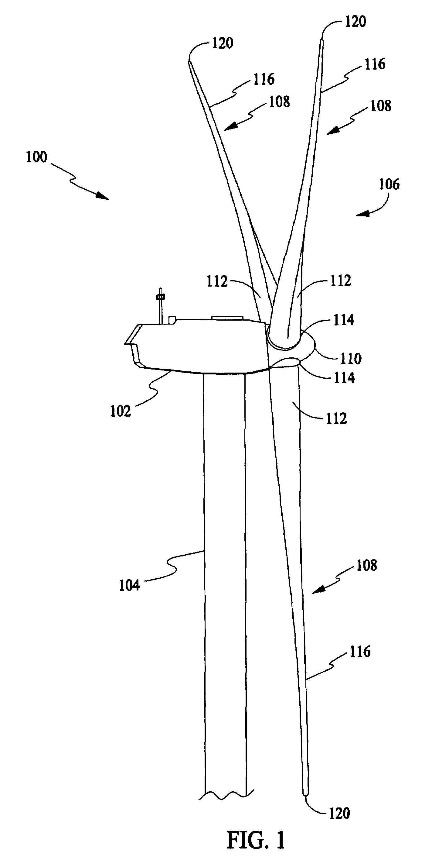
[0018]In some configurations and referring to FIG. 1, a wind turbine 100 in some configurations comprises a nacelle 102 housing a generator (not shown in FIG. 1). Nacelle 102 is mounted atop a tall tower 104, only a portion of which is shown in FIG. 1. Wind turbine 100 also comprises a rotor 106 that includes one or more rotor blades 108 attached to a rotating hub 110. Although wind turbine 100 illustrated in FIG. 1 includes three rotor blades 108, there are no specific limits on the number of rotor blades 108 required by the present invention.

[0019]Various components of wind turbine 100 in the illustrated configuration are housed in nacelle 102 atop tower 104 of wind turbine 100. The height of tower 104 is selected based upon factors and conditions know...


PUM

PropertyMeasurementUnit
lengthsaaaaaaaaaa
lengthsaaaaaaaaaa
lengthsaaaaaaaaaa

Abstract

A wind turbine includes a rotor having a hub and at least one blade having a torsionally rigid root, an inboard section, and an outboard section. The inboard section has a forward sweep relative to an elastic axis of the blade and the outboard section has an aft sweep.

Description

STATEMENT REGARDING FEDERALLY SPONSORED RESEARCH & DEVELOPMENT[0001]The U.S. Government has certain rights in this invention as provided for by the terms of Contract No. ZAM-7-13320-26 awarded by the Department of Energy, National Renewable Energy Laboratory Division, under Prime Contract No. DE-AC36-83CH10093 with the U.S. Department of Energy.BACKGROUND OF THE INVENTION[0002]This invention relates to blades that are particularly useful as wind turbine rotor blades and to rotors and wind turbines utilizing such blades.[0003]At least one known rotor blade configuration includes an aft-swept rotor blade design. When a wind gust strikes a blade with aft sweep, an increase in out-of-plane (flapwise) loading produces a pitching moment about sections further inboard. This pitching moment acts to induce outer portions of the blade to twist the leading edge of the blade sections into the wind so as to reduce an aerodynamic angle of attack of those sections, thereby ameliorating peak transi...

Claims


Application Information

Patent Timeline
Patent Type & Authority Patents(United States)
IPC IPC(8): F01D5/14
CPCF03D1/0633Y10T29/49336Y02E10/721F05B2240/30Y02E10/72Y02P70/50
Inventor WETZEL, KYLE KRISTOPHER
Owner GENERAL ELECTRIC CO
Why Eureka
Try Eureka