Putter type golf club

a golf club and putter technology, applied in golf clubs, sport equipment, golf, etc., can solve the problems of putter becoming more difficult to rotate, and achieve the effect of resisting twisting and maximizing rotational inertia

Active Publication Date: 2012-11-06
DEPAUL RICHARD
View PDF34 Cites 81 Cited by
  • Summary
  • Abstract
  • Description
  • Claims
  • Application Information

AI Technical Summary

Benefits of technology

[0011]It is an object of the invention to provide a putter that maximizes rotational inertia and thereby resists twisting. Accordingly, the putter is of the general type having a shaft having a top attached to a grip as well as a bottom attached to a putter head and then has improvements as discussed hereinafter. The putter head can be subdivided into a striking face that actually strikes the golf ball when making a putt, a main body, a main body top surface, main body bottom surface, and a main body rear. The striking face has a pair of striking face lateral edges.
[0013]It is a further object of the invention to increase the rotational inertia of the putter to a greater extent and further reduce its susceptibility to rotational forces. Accordingly in an embodiment of the invention, a cylindrical tail rod extending rearwardly from the main body rear is utilized to further increase rotational inertia. This tail rod is angled perpendicular to the striking face and between the heel and toe control wings, and is located closer to the top surface than to the bottom surface.
[0014]The putter's toe control wing, heel control wing, and tail rod maximize the amount of mass distributed as far away as possible from the horizontal center of mass to increase rotational inertia, thus making the putter more resistant to rotation and makes completing a shot easier. Just as how a figure skater turning on an axis speeds up when pulling her arms in and slows down when putting her arms out even though the total rotational energy of her body has not changed, by maximizing the amount of mass distributed away from the horizontal center of mass the putter becomes more difficult to rotate when rotational force is mistakenly inputted by the golfer's hands or by a golf ball being hit off center of the putter's face. This will add to the forgiveness of the golf club and facilitate the making of a clean putt. In effect, the invention maximizes the sweet spot of the striking face, making clean shots easier to make.
[0015]It is yet a further object of the invention to increase still the rotational inertia of the putter. Accordingly, another embodiment of the invention has matching recesses built into each control wing to further distribute mass to the outside of the putter head and away from the center of mass of the invention.

Problems solved by technology

Just as how a figure skater turning on an axis speeds up when pulling her arms in and slows down when putting her arms out even though the total rotational energy of her body has not changed, by maximizing the amount of mass distributed away from the horizontal center of mass the putter becomes more difficult to rotate when rotational force is mistakenly inputted by the golfer's hands or by a golf ball being hit off center of the putter's face.

Method used


Image

  • Putter type golf club
  • Putter type golf club
  • Putter type golf club

Examples


Embodiment Construction

[0027]Where used herein to refer to physical portions of the invention, the terms “heel” and “toe” with respect to the accompanying drawings, assume the invention described is used by a left-handed golfer. When used by a right-handed golfer all such descriptions will be reversed, as such terms are essentially interchangeable provided their usage remains consistent.

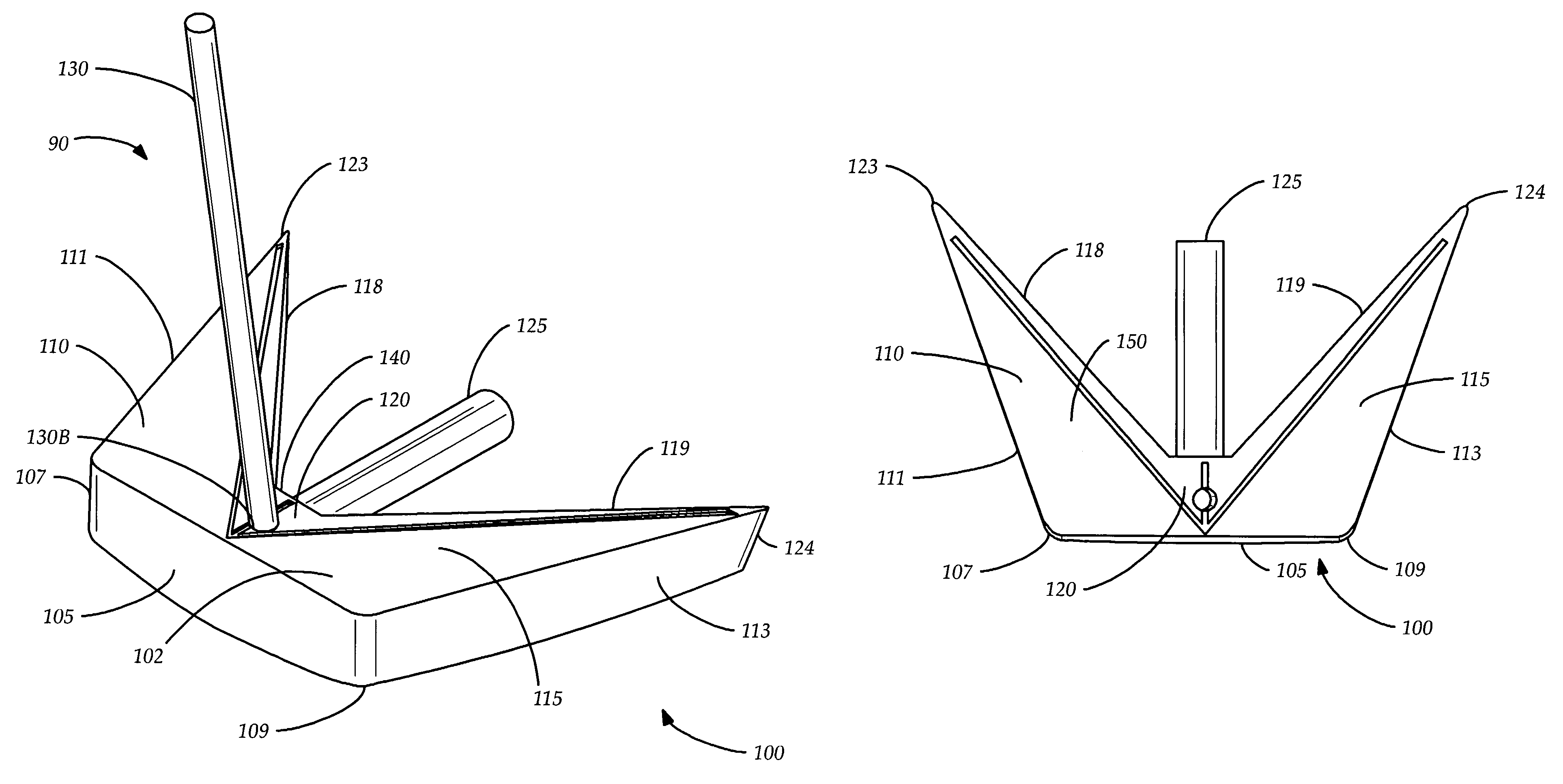
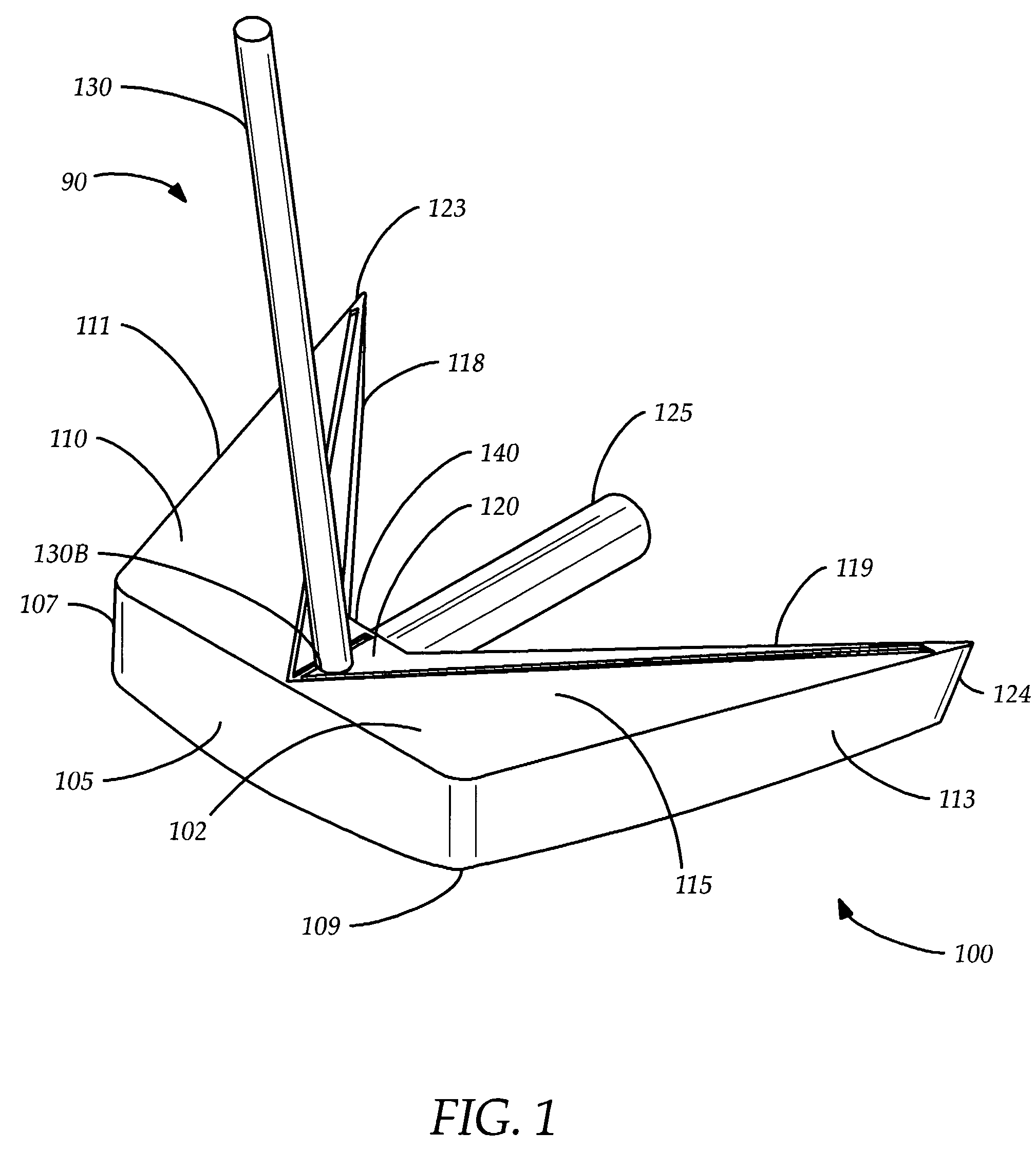
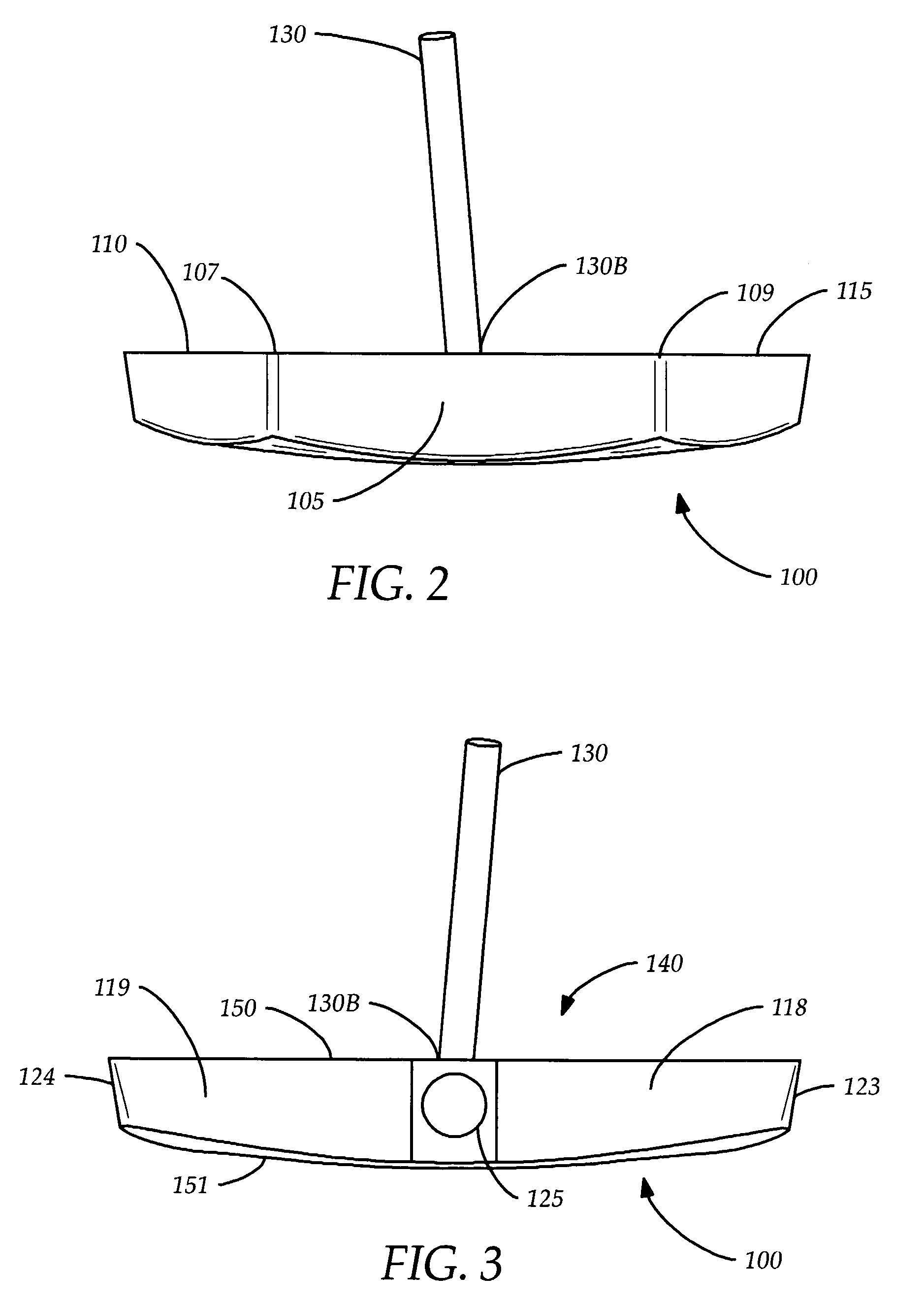
[0028]FIG. 1 illustrates a putter 90 in accordance with the principles of the present invention, having a putter head 100 and a shaft 130. The shaft 130 has a bottom 130B which is attached to the putter head 100. The putter head 100 has a shaft connection hole 120, where the bottom 130B of the shaft 130 is attached. The putter head 100 also has a main body 102, having a top surface 150, a bottom surface 151, a main body rear 140, and a front striking face 105 which is that part that actually strikes a golf ball when making a putt.

[0029]In accordance with the principles of the present invention, the putter head also has a h...


PUM


Abstract

A putter golf club that resists twisting by increasing the rotational inertia of the golf club to the maximum degree possible by distributing mass away from the center of mass of the putter, and thereby expands the sweet spot of the putter. Rotational inertia is maximized via use of a heel control wing and a toe control wing extending rearwardly and outwardly from a striking face of the putter as well as a tail rod extending perpendicularly from striking face. Further increase of rotational inertia is accomplished via s symmetrical recesses incorporated into heel and toe control wing.

Description

CROSS REFERENCES AND RELATED SUBJECT MATTER[0001]This application relates to subject matter contained in patent application Ser. No. 29 / 315,270, filed in the United States Patent Office on Jun. 10, 2009.BACKGROUND OF THE INVENTION[0002]The invention relates to a putter golf club. More particularly, it relates to a putter golf club where mass has been distributed away from the putter's horizontal center of mass to aid in resisting unintended rotation when a putt is made and thereby facilitate making straight putts.[0003]Putting is an under-appreciated art in the world of golf. As a result, many golfers put more thought into the selection of their drivers and irons than the selection of their putters. Despite this, on average more than 40% of all golf shots are putts, and it is undeniable that efficient putting is essential to a good game of golf.[0004]In the physics of golf putting, in order to putt a golf ball in the most straight and therefore predictable manner it is necessary for...

Claims


Application Information

Patent Timeline
Patent Type & Authority Patents(United States)
IPC IPC(8): A63B53/04
CPCA63B53/0487A63B2053/0441A63B2053/0437A63B2053/0433A63B53/0433A63B53/0437A63B53/0441
Inventor DEPAUL, RICHARD
Owner DEPAUL RICHARD
Why Eureka
Try Eureka