Garment hanger with central support rib

a technology of central support and garment hangers, which is applied in the field of garment hangers, can solve the problems of rippling or other undesirable marring of the exposed surface of the arms of the hangers, increasing the time and cost of manufacturing such hangers, and even breaking the transition region under heavy garment loads, so as to increase the resistance to twisting. , the effect of increasing strength and stability

Inactive Publication Date: 2007-07-31
SPOTLESS PLASTICS PTY LTD
View PDF18 Cites 1 Cited by
  • Summary
  • Abstract
  • Description
  • Claims
  • Application Information

AI Technical Summary

Benefits of technology

[0014]Positioning the support rib between the underside of the various panels at a single location minimizes rippling, waving or other undesirable distortions or marring of the exposed surfaces of the hanger. Further, the use of a single support rib minimizes the time and costs associated with making the hanger according to the invention. Moreover, because the support rib of the invention extends between panels comprising the arm, shoulder and central hook regions, increased stability is provided to the hanger notwithstanding the absence of additional reinforcing channels or I-sections on or in the hanger arms as in prior art hangers.
[0016]By extending through the hanger in this manner at the interface of the arm, shoulder and central hook regions, the support rib resists twisting even under heavy garment loads. Wings are provided to connect the exposed portion of the receiving end of the support rib to the hanger to increase the resistance to twisting and to provide even greater strength and stability therefore. Incorporating the support rib into a garment hanger according to the invention thus provides a garment hanger of increased strength and stability that is easy and inexpensive to manufacture.

Problems solved by technology

Though the strength and durability of the wooden hangers, in particular, were appealing, the increased costs and additional weight of the wooden hangers resulted in the development of less expensive and lighter weight plastic hangers, such as those disclosed in Australian Patent No. 544211 (AU-B-21403 / 83) or U.S. Pat. No. 5,071,045 that are commonly-owned herewith.
Moreover, where less flexible material, such as general purpose polystyrene, has been used to comprise the molded plastic hangers, the transition regions may even break under heavy garment loads.
In any event, incorporation of such channel inserts or I-sections throughout, or at various intervals of, the arms of the hanger increase the time and costs to manufacture such hangers.
Additionally, the co-molding or other provision of the channels or I-sections to the arms of the hangers often cause rippling or other undesirable marring of exposed surfaces of the arms of the hangers, particularly where the channels or I-sections are located only at various intervals of the arms of the hangers.
Moreover, experiments have shown that the use of such channel inserts or I-sections tend still to create regions of weakness in the hanger.
The weak regions render the hangers susceptible to bending or breaking as before, particularly at the transition region between the central hook and shoulder regions, when the hanger experiences heavy loads.
The external channels or depressions are intentionally isolated from the channels of the arms, however, which renders the hangers susceptible to twisting.
Such twisting can result in bending or breaking of the hanger as well.

Method used


Image

  • Garment hanger with central support rib
  • Garment hanger with central support rib
  • Garment hanger with central support rib

Examples


Embodiment Construction

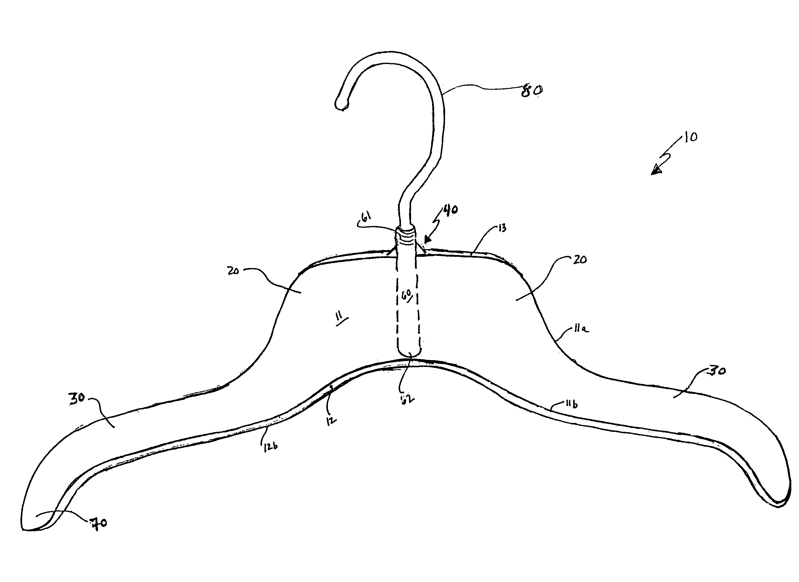
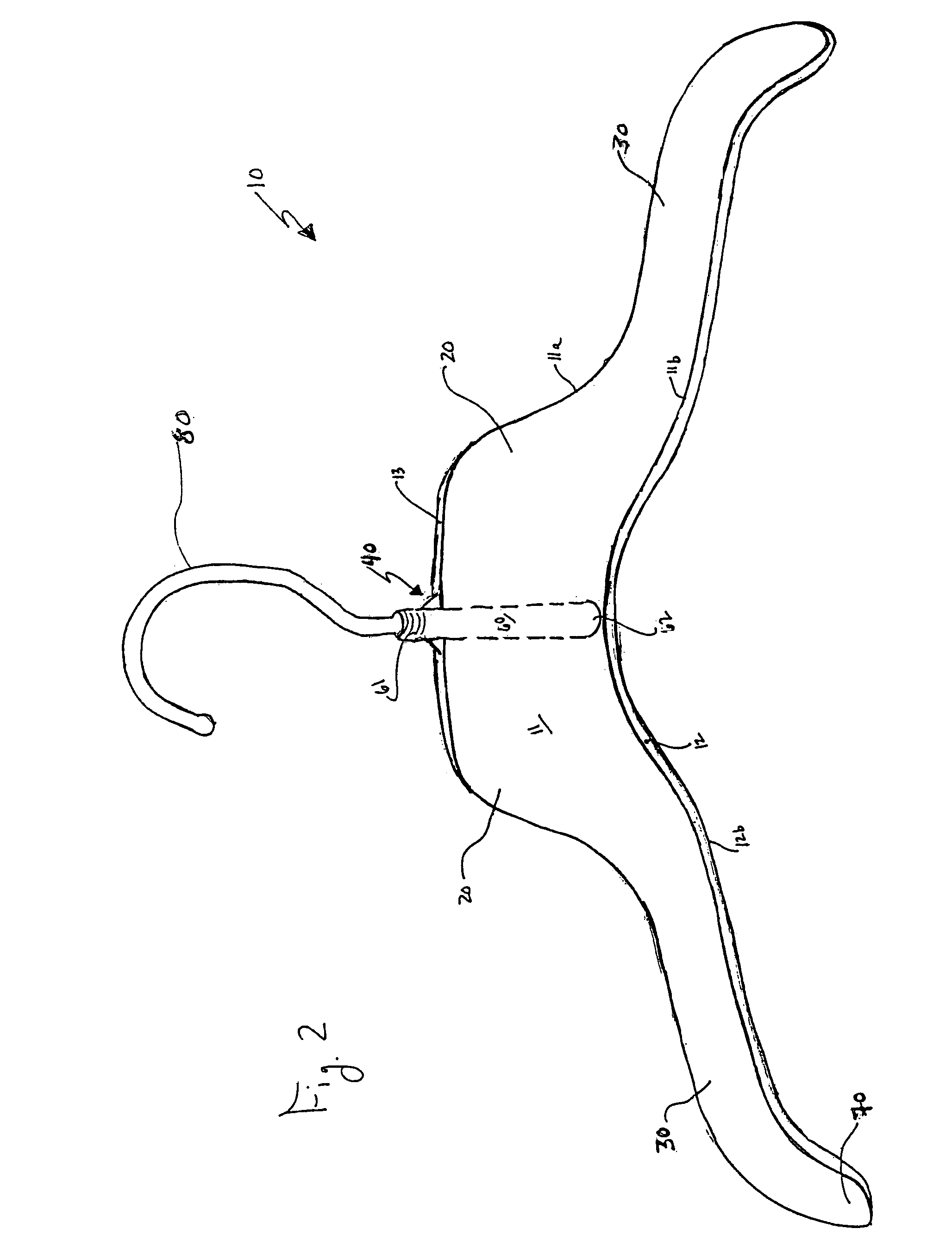
[0025]FIG. 2 illustrates a perspective view of a generally open-channeled garment hanger 10 according to the invention. The garment hanger 10 comprises a shoulder region 20, an arm region 30, and a central hook region 40. The shoulder, arm and central hook regions are formed generally as an inverted unshaped channel from a first panel 11 and a second panel 12 joined by a third panel 13.

[0026]The first panel 11 has an upper edge 11a and a lower edge 11b. The second panel has an upper edge (12a not shown) and a lower edge 12b that generally correspond to the upper edge 11a and the lower edge 11b of the first panel, respectively. The second panel 12 is positioned substantially parallel to and spaced apart from the first panel 11, wherein the third panel 13 joins the first panel 11 and the second panel 12 along the respective upper edges 11a and 12a thereof. Joining the first panel 11 and the second panel 12 with the third panel 13 in this manner helps to maintain the first panel 11 and...


PUM

PropertyMeasurementUnit
frictionaaaaaaaaaa
strengthaaaaaaaaaa
stabilityaaaaaaaaaa

Abstract

An easily and inexpensively manufactured garment hanger of increased strength and durability. The garment hanger comprises a suspension hook secured to a support rib provided at a central hook region of the hanger. Incorporating the support rib through the central hook region of the hanger minimizes twist and other distortions of the hanger, even when under heavy garment loads.

Description

CROSS-REFERENCE TO RELATED APPLICATIONS[0001]Under 35 U.S.C. § 119(e), this application claims priority of U.S. Provisional Patent Application Ser. No. 60 / 665,940 filed 29 Mar. 2005, entitled Garment Hanger with Central Support Rib the disclosure of which is hereby incorporated by reference in its entirety for all purposes.BACKGROUND OF THE INVENTION[0002]1. Field of the Invention[0003]The invention generally relates to garment hangers. More specifically, the invention relates to molded plastic garment hangers having a rib support structure at an interface of shoulder, arm and central hook regions of the hanger.[0004]2. Related Art[0005]Garment hangers have been known and used for years. Historically, as shown in FIG. 1, the basic garment hanger 1 was wire or wooden having opposed shoulders 2 joined at a central hook region 3. A suspension hook 4 projects from the central hook region 3 permitting the hanger 1 to be placed on a rod or other structure for storage in a closet, for exam...

Claims


Application Information

Patent Timeline
Patent Type & Authority Patents(United States)
IPC IPC(8): A41D27/22
CPCA47G25/32A47G25/14A47F7/24A47G25/36
Inventor GOULDSON, STANLEY
Owner SPOTLESS PLASTICS PTY LTD
Why Eureka
Try Eureka