Stage device

a stage device and stage technology, applied in the direction of mechanical measuring arrangements, instruments, photomechanical devices, etc., can solve the problems of large error of position in the perpendicular direction, response speed and measurement accuracy, and the weight of the device itself becomes heavy

Inactive Publication Date: 2007-02-15
SUMITOMO HEAVY IND LTD +1
View PDF4 Cites 139 Cited by
  • Summary
  • Abstract
  • Description
  • Claims
  • Application Information

AI Technical Summary

Benefits of technology

[0023] According to one aspect of the invention, there is provided an improved stage device in which the above-mentioned problems are eliminated. According to one aspect of the invention, there is provided a stage device which can attain the miniaturization of the stage device and can perform the measurement of a position of the stage to the base with high accuracy.
[0025] The present invention can provide a stage device which attains the miniaturization of the stage device and performs measurement of a position of the stage to the base with high accuracy.
[0027] Since there is no guide structure of the shaft and the planar motor which can control the X-direction movement, the Y-direction movement and the rotational movement around the Z axis is used, it is possible that the weight of the stage device be saved and the manufacturing cost be reduced.
[0030] Since the two-dimensional angle sensors have a dead pass which is very small when compared with the conventional laser interferometer, they are unlikely to be influenced by the instrumentation error due to thermal expansion, fluctuation of air, etc. Therefore, it is possible to perform high-accuracy position and attitude measurement.

Problems solved by technology

Since it is necessary for the stack type stage device to have a high-horizontal rigidity, and there is a problem that the weight of the device itself becomes heavy and a large error of the position in the perpendicular direction may occur due to the influence of the weight.
However, the level vial has a problem in the response speed and measurement accuracy, and it is unsuitable for a high accuracy measuring device.
However, the following problems arise in the stage device using the above-mentioned conventional position measuring device.
And the design of a moving body position measuring device has a considerable constraint in the structure thereof.
Consequently, when the position measuring device of this kind is provided in the stage device, there is a constraint in the structure thereof, and the manufacturing cost becomes high.

Method used


Image

  • Stage device
  • Stage device
  • Stage device

Examples


first embodiment

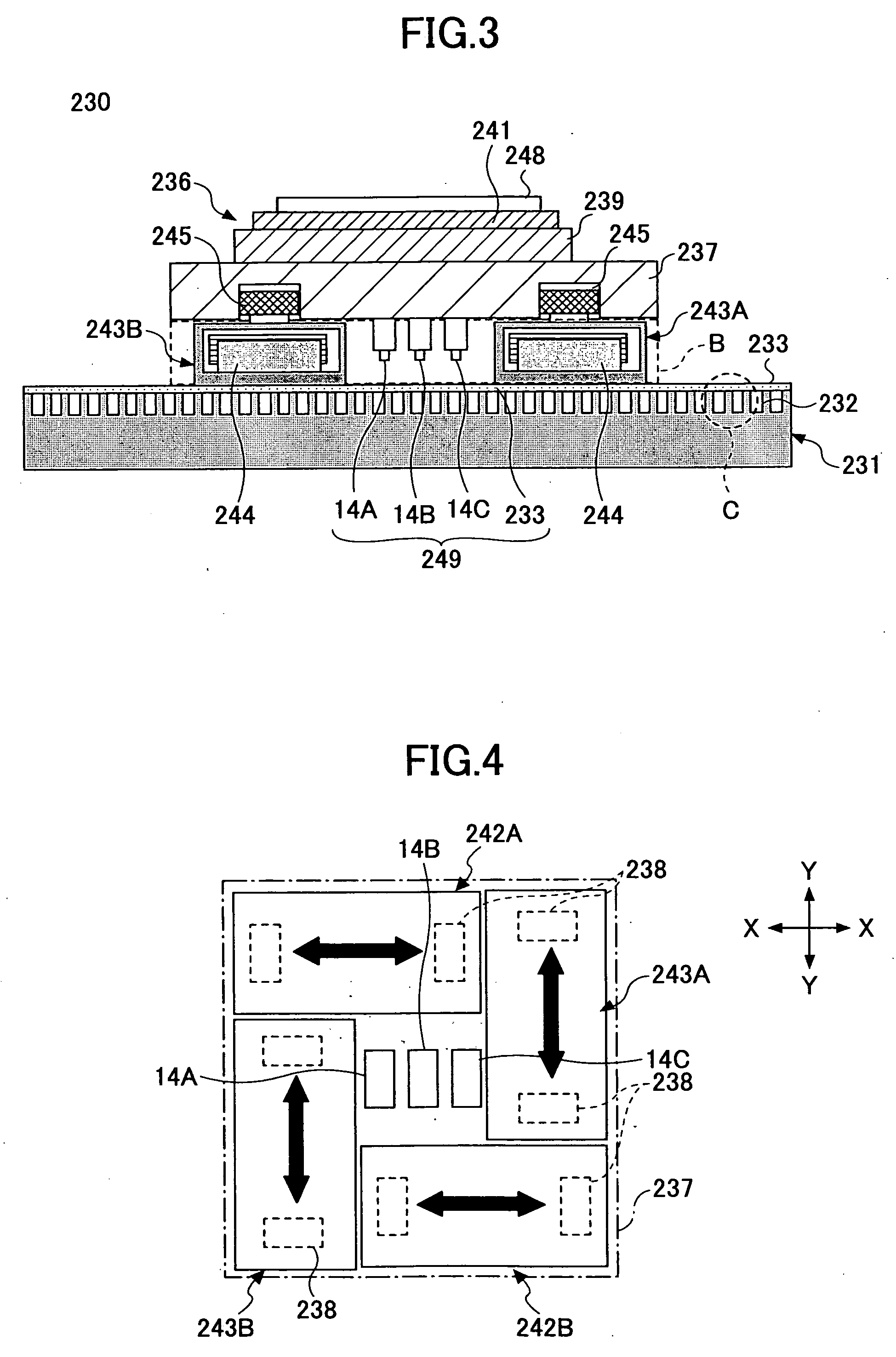
[0050] First, with reference to FIG. 3 and FIG. 4, the stage device 230 in the invention will be explained.

[0051]FIG. 3 is a cross-sectional diagram of the stage device of the first embodiment, and FIG. 4 is a plan view of the structure of the stage device corresponding to the area B indicated in FIG. 3.

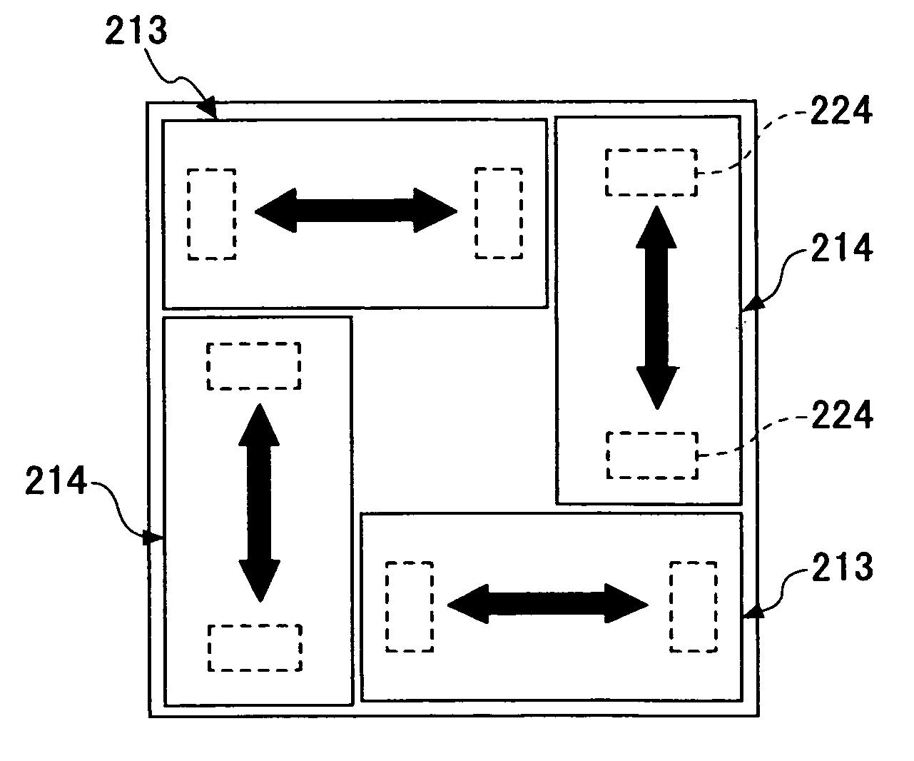
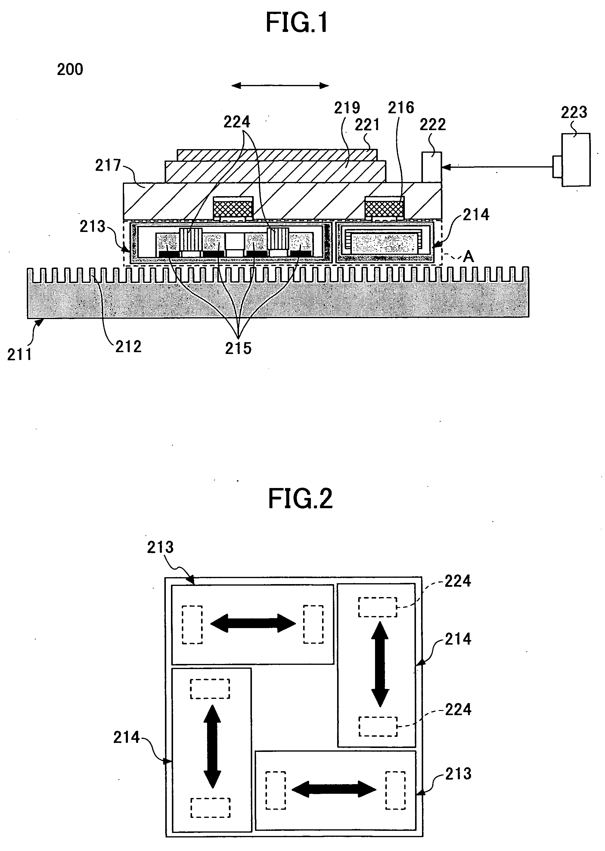
[0052] The stage device 230 is a stage device having a SAWYER motor drive part. The stage device 230 comprises a base 231, a stage 236, and a surface encoder 249 as shown in FIG. 3. A plurality of convex parts 232 are formed on the surface of the base 231 at a predetermined pitch. This predetermined pitch is equivalent to the minimum unit of length by which a movable stage part 237 can be moved. The base 231 is made of a metal, such as iron. The stage 236 comprises a movable stage part 237, a fixed stage part 239, a chuck 241, X-direction actuators 242A and 242B, Y-direction actuators 243A and 243B, and tilt actuators 245.

[0053] The movable stage part 237 is a base part which is dr...

second embodiment

[0092] Next, a description will be given of the stage device 10 in the invention with reference to FIG. 10 and FIG. 11.

[0093]FIG. 10 is an exploded perspective view of the stage device 10 in the second embodiment of the invention, and FIG. 11 is a partially cut-away perspective view of the stage device 10 which is in the assembled condition.

[0094] The stage device 10 is provided for moving the wafer, which is a movable body in the stepper in the semiconductor manufacturing process, to a predetermined position.

[0095] The stage device 10 comprises the base 11, the stage 12, the surface encoder 24, the drive unit, etc. The base 11 serves as the base of the stage device 10, and the linear motor structure parts 20A and 25A, the Z-direction electromagnet 30, and the two-dimensional angle sensors 14A-14C, etc. which will be described later are disposed on the base 11.

[0096] In the present embodiment, the case in which the two-dimensional angle sensors 14A-14C used in the first embodimen...


PUM

PropertyMeasurementUnit
heightaaaaaaaaaa
heightaaaaaaaaaa
angleaaaaaaaaaa

Abstract

This invention relates to a stage device which is moved with high accuracy in an X-Y direction and a rotating direction using a planar motor. The invention is aimed at reducing the size of the stage device and at performing accurately measurement of a position of the stage to the base. The stage device comprises a scale unit having a scale part on the entire plane of the base, and three two-dimensional angle sensors disposed on a bottom surface of a movable stage part. The scale unit and the two-dimensional angle sensors form a surface encode. A position of the movable stage part is measured by the surface encoder.

Description

CROSS-REFERENCE TO RELATED APPLICATION [0001] This application is a U.S. continuation application which is filed under 35 USC 111(a) and claims the benefit under 35 USC 120 and 365(c) of International Application No. PCT / JP2005 / 004757, filed on Mar. 17, 2005, the entire contents of which are hereby incorporated by reference.BACKGROUND OF THE INVENTION [0002] 1. Field of the Invention [0003] The present invention generally relates to a stage device, and more particularly to a stage device which is moved with high accuracy in a X-Y direction and a rotating direction by using a planar motor. [0004] 2. Description of the Related Art [0005] Concerning ultra-precision machining devices and semiconductor devices which are the basis of information processing technology, the demand for high-accuracy positioning and high-speed processing of stage devices, used for these devices, is increasing. For example, for the stage device which is a key component of a semiconductor exposure device, the p...

Claims


Application Information

Patent Timeline
Patent Type & Authority Applications(United States)
IPC IPC(8): B64C17/06G01B11/00G01B11/26G03F7/20H01L21/027H01L21/68H02K41/03
CPCG03F7/70775G03F7/70716H01L21/68
Inventor GAO, WEIKIYONO, SATOSHITOMITA, YOSHIYUKITANO, MAKOTO
Owner SUMITOMO HEAVY IND LTD
Why Eureka
Try Eureka