Dust boot with grease relief passage

Active Publication Date: 2007-03-01
FEDERAL MOGUL WORLD WIDE LLC
View PDF23 Cites 17 Cited by
  • Summary
  • Abstract
  • Description
  • Claims
  • Application Information

AI Technical Summary

Benefits of technology

[0011] As grease is flushed from the dust boot, it is directed along a path defined by the grease relief passage. If a dust boot becomes pinched during stud articulation, the grease relief passage provides an escape path for grease after it passes the flap. Accordingly, even if the dust boot becomes compressed so that a fold develops in the body of the dust bo

Problems solved by technology

These “lube-for-life” parts are low maintenance since they are sealed, but generally do not have the longevity of a “greaseable” part.
One challenge faced when designing a dust boot for a greaseable part is that the dust boot must serve as a barrier to prevent contamination from entering the articulating component.
In other words, the compression of the boot, particularly in the

Method used


Image

  • Dust boot with grease relief passage
  • Dust boot with grease relief passage
  • Dust boot with grease relief passage

Examples


Example

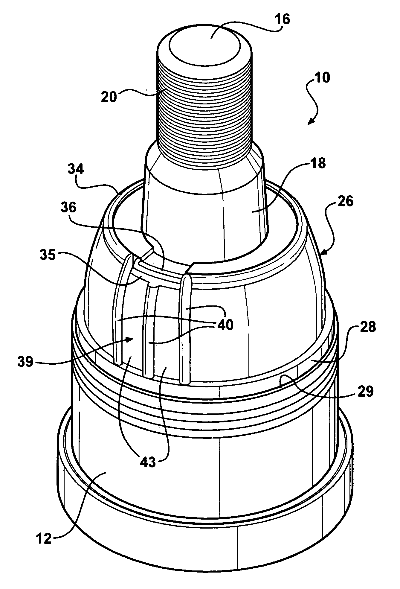
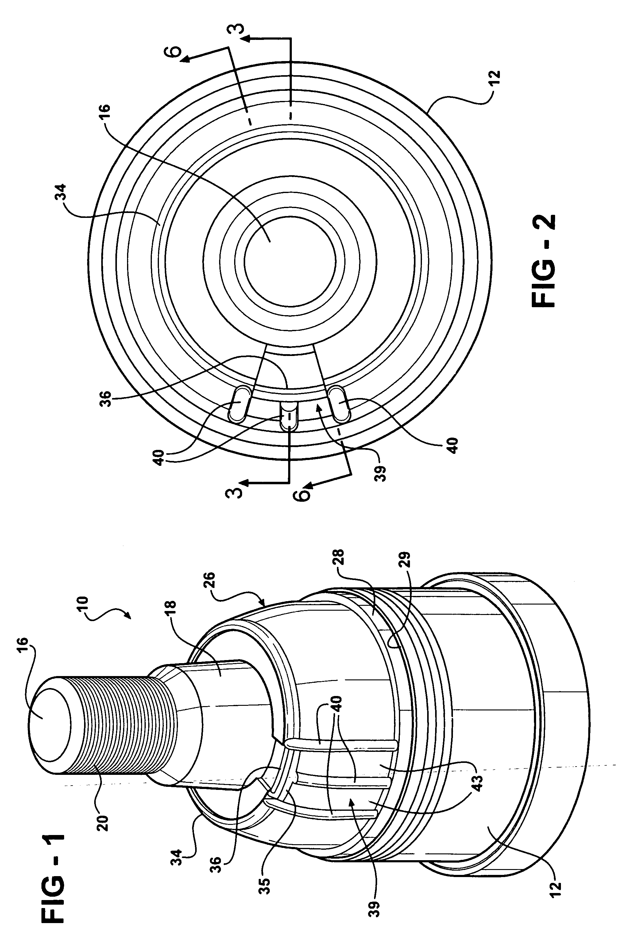
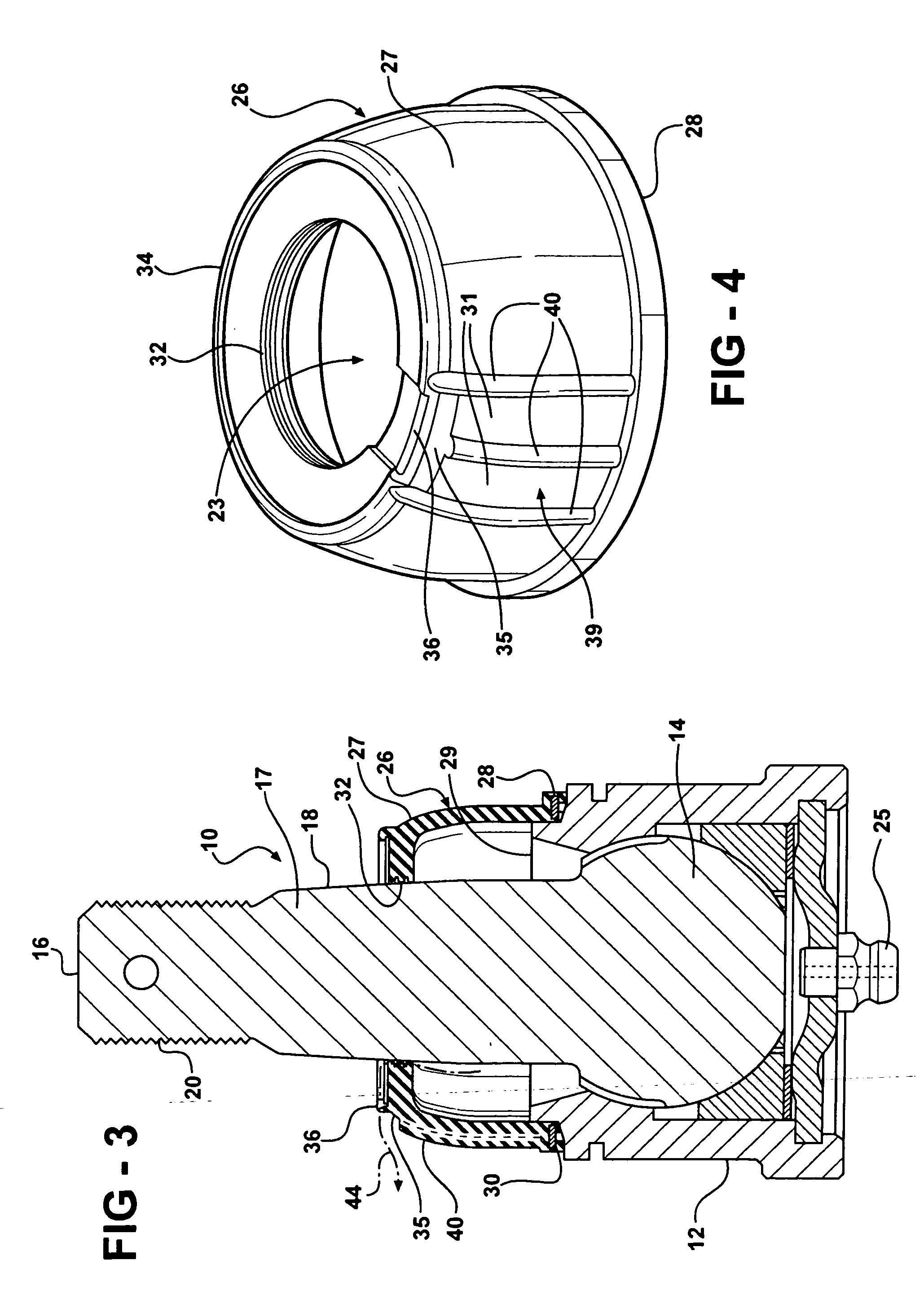
[0021] A typical ball joint assembly is generally shown at 10 in FIGS. 1, 2, 3, 6, 7 and 8, and in an alternate arrangement in FIG. 9. The ball joint assembly 10 includes a cup-like housing 12, preferably formed from a metal such as steel, in which is captured the articulating ball portion 14 of a ball stud 16, also preferably formed from a metal such as steel. The ball stud 16 also includes a shank portion 17 that extends integrally from the ball portion 14, outwardly from the housing 12. The shank portion 17 has a tapered connection surface 18 and a threaded end 20. As shown in FIGS. 7 and 8, a control arm 22 may be joined to the tapered connecting surface 18 of ball joint assembly 10 and secured into position via nut 24. Instead of the depicted control arm 22, another anchoring feature such as a knuckle, spindle, link or frame or other chassis component may be used. The joint is adapted to receive grease or other lubricant through grease fitting 25

[0022] Referring to FIGS. 4 and ...


PUM


Abstract

A joint enclosure apparatus includes a dust boot having an opening and a rim located adjacent to the opening, a flexible flap formed as a portion of the rim, and at least one grease relief passage located on an outer surface of the dust boot adjacent to the flexible flap. The dust boot is useful for use in a ball joint assembly which includes a ball stud having a shank portion and a ball portion; a housing adapted to receive the ball portion in articulatable engagement in a ball stud exit end; a dust boot having a shank opening in sealing engagement with the shank portion and a housing opening in sealing engagement with the housing at the ball stud exit end and a rim adjacent to the shank opening; a flexible flap formed as a portion of the rim; and at least one grease relief passage located on an outer surface of the dust boot adjacent to the flexible flap. The grease relief passage may comprise a rib or a recessed channel. The area of the outer surface of the dust boot adjacent to the flexible lip may be undercut to control the relief characteristics of the flexible lip. As grease is flushed from the dust boot, it is directed along a path defined by the grease relief passage. If a dust boot becomes pinched during stud articulation, the grease relief passage provides an escape path for grease after it passes the flap.

Description

CROSS-REFERENCE TO RELATED APPLICATIONS [0001] This patent application claims priority to U.S. Provisional Patent Application Ser. No. 60 / 711,207, filed Aug. 25, 2005, which is incorporated herein by reference in its entirety.BACKGROUND OF THE INVENTION [0002] 1. Field of the Invention [0003] This invention relates to a boot type seal especially adapted for ball and socket type joints. More particularly, it relates to a boot type seal for ball and socket type joints having a grease relief passage or passages on an outer surface thereof. [0004] 2. Related Art [0005] Nearly all original chassis equipment, such as ball joints and tie rod ends, are sealed units. These “lube-for-life” parts are low maintenance since they are sealed, but generally do not have the longevity of a “greaseable” part. A greaseable part is one in which additional grease may be added periodically to replace grease which has escaped or broken down during use, thereby flushing old grease, debris associated with we...

Claims


Application Information

Patent Timeline
IPC IPC(8): F16C11/00
CPCF16C11/0671F16J3/046Y10S277/928Y10T403/32729Y10T403/32631Y10T403/31
Inventor ELTERMAN, JAMESKARPMAN, ALEXANDER
Owner FEDERAL MOGUL WORLD WIDE LLC
Why Eureka
Try Eureka