Rate tube measurement system

a measurement system and rate tube technology, applied in the direction of relative volume flow measurement, machines/engines, instruments, etc., can solve the problems of not being suitable for manufacturing assembly line environment, not suitable for use in assembly line environment, and conventional rate tube measurement systems are not designed to measure fueling, etc., to achieve accurate measurement of the amount of fuel injected

Active Publication Date: 2006-07-25
CUMMINS INC
View PDF11 Cites 20 Cited by
  • Summary
  • Abstract
  • Description
  • Claims
  • Application Information

AI Technical Summary

Benefits of technology

[0009]In view of the foregoing, one aspect of the present invention provides a measurement system for accurately measuring the amount of fuel injected by a fuel injector.

Problems solved by technology

While positive displacement, piston type measurement systems are sufficiently accurate to measure the amount of fuel in the pilot and / or post injections as well as the primary injection in multi-pulse common rail injection systems, they are typically very complex and costly.
Consequently, such positive displacement, piston type measurement systems, are not suitable for use in the manufacturing assembly line environment where numerous systems are required to test a significant number of fuel injectors.
However, conventional rate tube measurement systems are not designed to measure fueling in multi-pulse common rail injection systems.
In particular, conventional rate tube measurement systems are not adapted to measure the amount of fuel injected during pilot and / or post injections, as well as the primary injection.
However, the measurement system disclosed requires complex processing and filtering of the captured sensor output in order to derive information regarding the injection event such as fuel injection quantity, variation, and / or rate shape.
However, development of such filters and methods for processing the acquired sensor output is expensive.
In addition, such filtering and processing of the acquired sensor output can decrease the accuracy of the system since the quality of the filters and methods used to process the acquired sensor output can render the results inaccurate.
Furthermore, because the system disclosed in the SAE Paper is designed for use in a laboratory environment where technicians can take their time in conducting the desired experiments, there are no provisions or features for expediting the measurement of the fuel injected by the fuel injector being tested.
Therefore, there exists an unfulfilled need for a measurement system for accurately measuring the amount of fuel injected by a fuel injector.
There also exists an unfulfilled need for such a measurement system that provides accurate injection measurements, but reduces the filtering and processing requirements that are required for prior art systems.

Method used


Image

  • Rate tube measurement system
  • Rate tube measurement system
  • Rate tube measurement system

Examples


Embodiment Construction

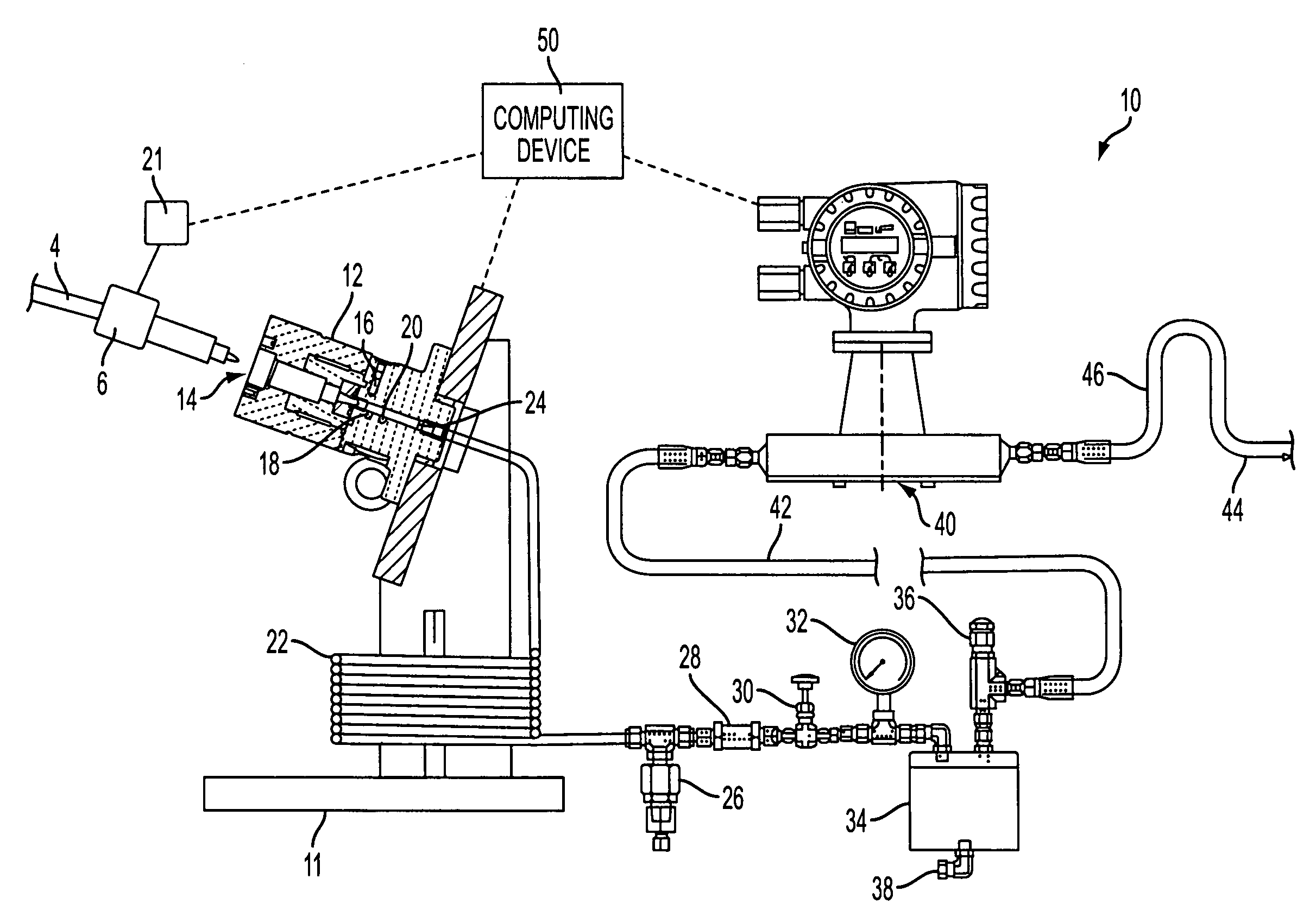
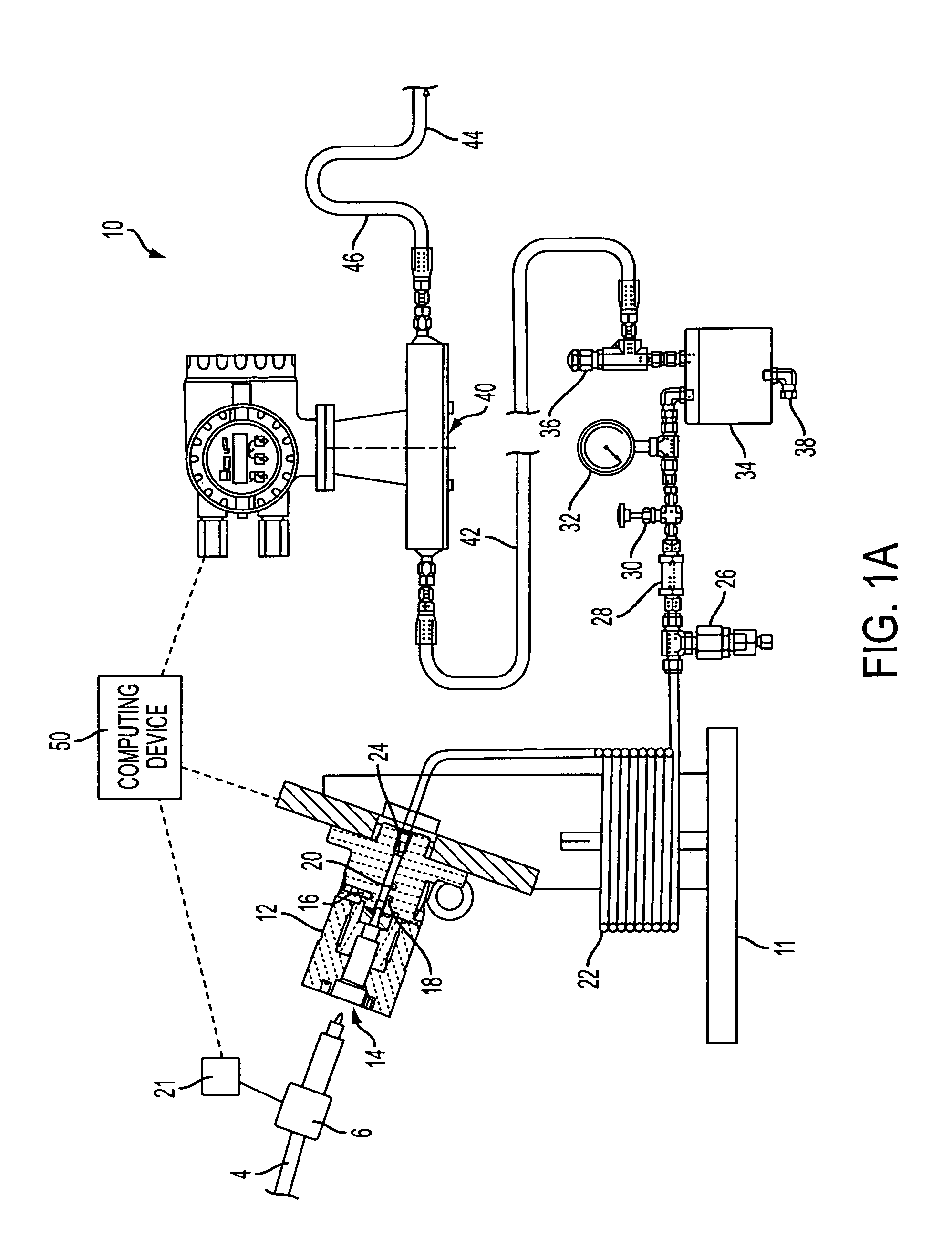
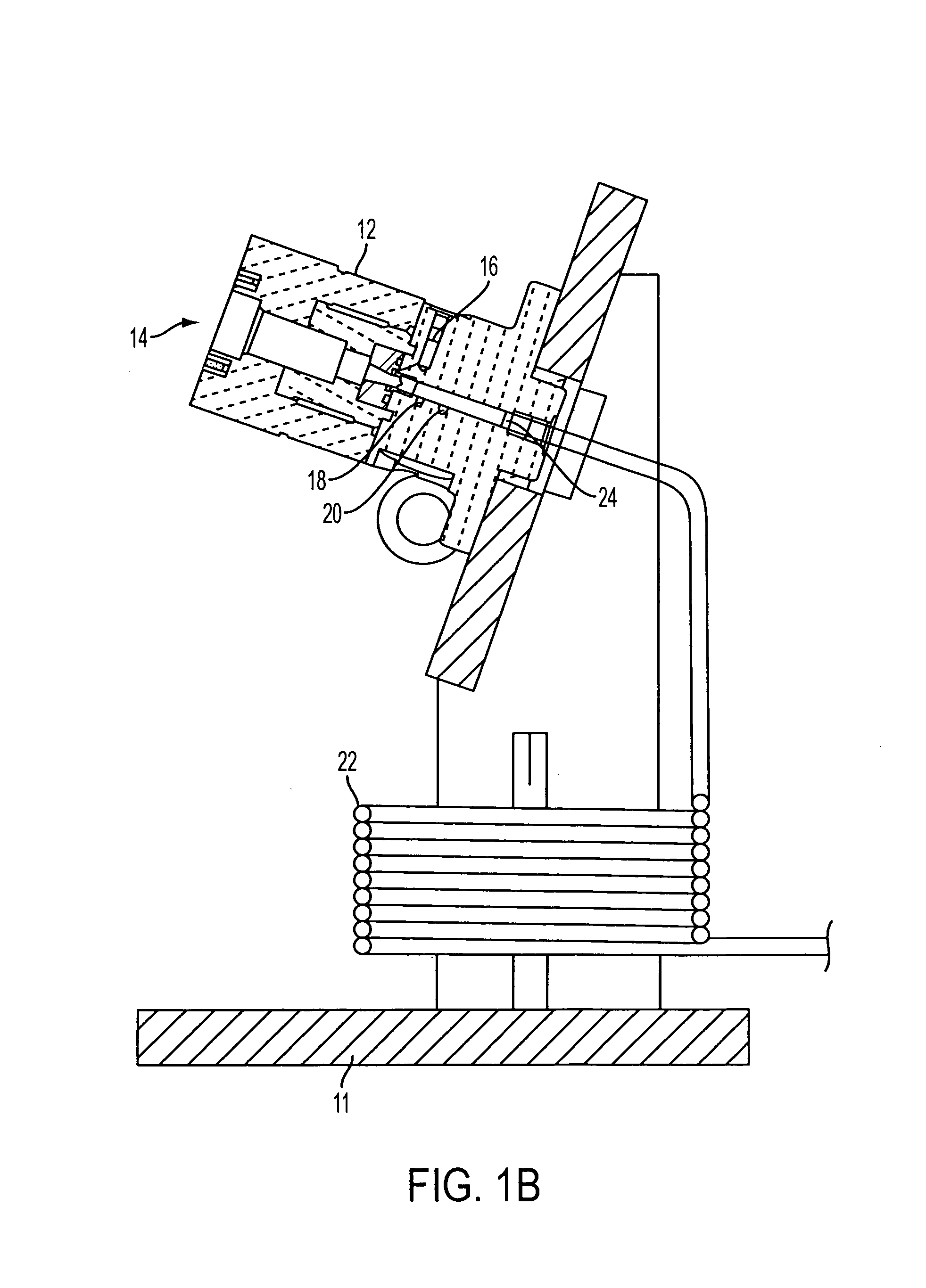
[0024]FIGS. 1A and 1B show a schematic illustration of a rate tube measurement system 10 in accordance with one embodiment of the present invention, these figures being discussed together herein. As will be described in detail below, the rate tube measurement system 10 can be advantageously used to accurately measure injection rate of multi-pulse common rail injection systems. As noted, multi-pulse common rail injection systems actuate fuel injectors to provide pilot injections and / or post injections in addition to the primary injection during an injection event. As discussed in further detail below, the rate tube measurement system 10 is adapted to measure the fuel injection quantity, variation, and / or rate shape of the multi-pulse injections, such measurements not being economical or practical with prior art positive displacement piston type measurement systems. In addition, the present invention attains these measurements with minimal filtering and / or processing as compared to pr...


PUM


Abstract

A rate tube measurement system for measuring injected fuel and a method thereof are disclosed. In one embodiment, the system includes a fixture assembly, a rate tube fluidically connected to the fixture assembly to receive fuel injected by the fuel injector during, a pressure sensor positioned upstream of the rate tube that is adapted to measure pressure changes in the injected fuel and provide a pressure output, a flow meter that measures flow of injected fuel and provides a flow output indicative of the measured fuel flow, and a computing device that processes the duration of actuation, the pressure output and the flow output to determine injection information such as fuel injection quantity, variation, and rate shape.

Description

[0001]This application claims priority to U.S. Provisional Application No. 60 / 494,562, filed Aug. 13, 2003, the contents of which are incorporated herein by reference.BACKGROUND OF THE INVENTION[0002]1. Field of the Invention[0003]The present invention is directed to a rate tube measurement system for measuring fuel injected by a fuel injector.[0004]2. Description of Related Art[0005]The development of multi-pulse common rail injection systems in which fuel injectors are actuated to provide pilot and / or post injections as well as the primary injection has prompted the need for new, end-of-the-line, functional test equipment that can measure the fuel injected by the fuel injector. While positive displacement, piston type measurement systems are sufficiently accurate to measure the amount of fuel in the pilot and / or post injections as well as the primary injection in multi-pulse common rail injection systems, they are typically very complex and costly. Consequently, such positive disp...

Claims


Application Information

Patent Timeline
Patent Type & Authority Patents(United States)
IPC IPC(8): F02M65/00F01L1/46G01M15/00
CPCF02M65/003
Inventor GORIS, NORMAN H.RAUZNITZ, TAMASAWAD, JOHN K.
Owner CUMMINS INC
Why Eureka
Try Eureka