

Crankcase ventilation for turbocharged engine
- Summary
- Abstract
- Description
- Claims
- Application Information
AI Technical Summary
Benefits of technology
Problems solved by technology
Method used
Image

Examples
Embodiment Construction
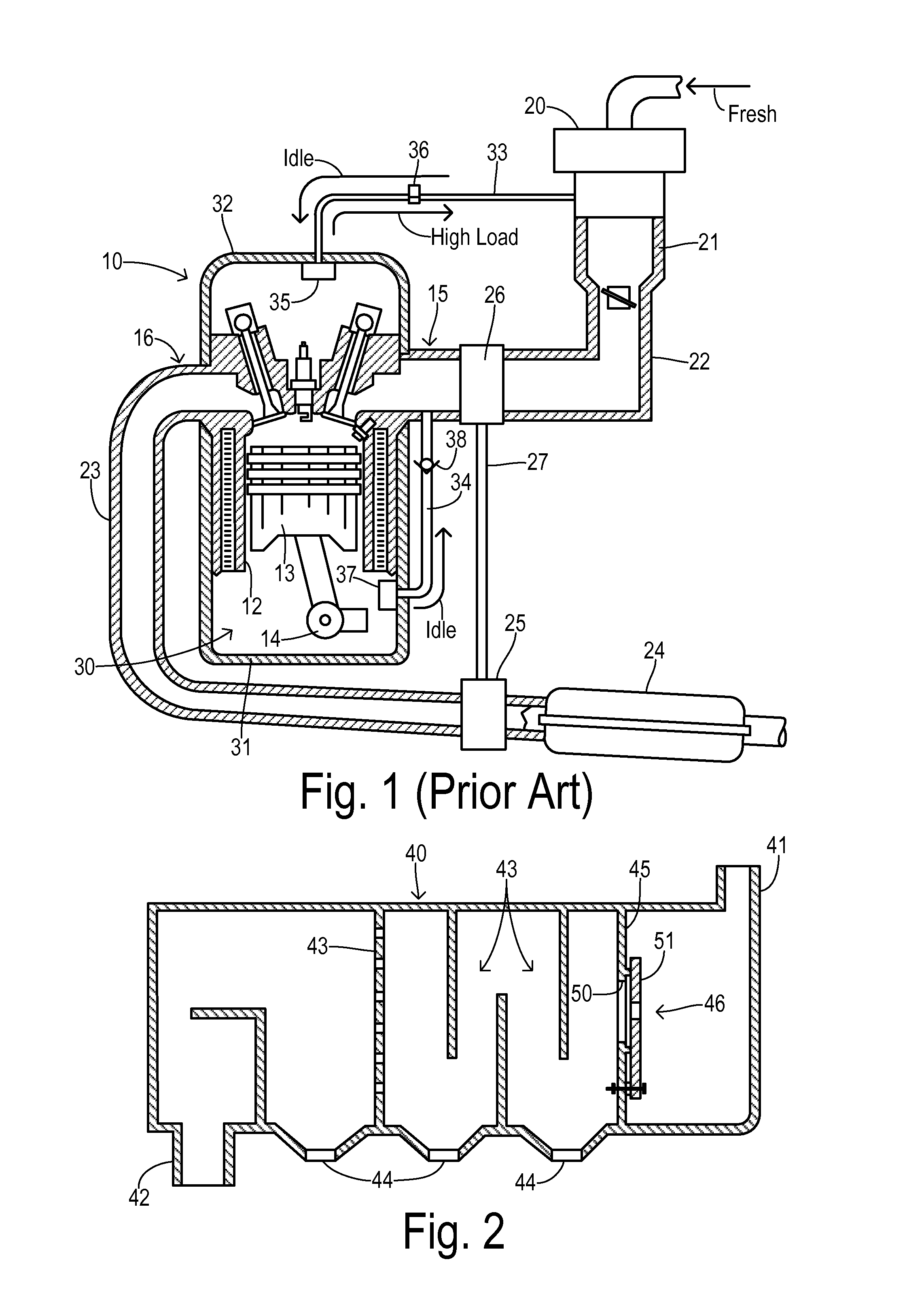
[0018]Referring to FIG. 1, an internal combustion engine 10 in an automotive vehicle includes a plurality of cylinders. One cylinder is shown, which includes a combustion chamber 11 and cylinder walls 12 with piston 13 positioned therein and connected to crankshaft 14. Combustion chamber 11 communicates with an intake manifold 15 and exhaust manifold 16 via respective intake and exhaust valves operated by respective cams.
[0019]Engine 10 may preferably utilize direct fuel injection and an electronic distributorless ignition system as known in the art. Fresh outside air is conducted to engine 10 via an air filter 20, a throttle body 21, and an air inlet duct 22 connected to intake manifold 15. Combustion products exiting exhaust manifold 16 are conducted via a conduit 23 to a catalytic converter 24 on their way to an exhaust system (not shown). A turbocharging system is comprised of a turbine 25 positioned in the exhaust gas flow before catalytic converter 24 and coupled to a compress...
PUM
 Abstract
Description
Claims
Application Information