Indicator panel and method of manufacturing the same

Active Publication Date: 2007-03-29
DENSO CORP
View PDF11 Cites 20 Cited by
  • Summary
  • Abstract
  • Description
  • Claims
  • Application Information

AI Technical Summary

Benefits of technology

[0017] Accordingly, in the first, second or third embodiment, a crack and a removal of the des

Problems solved by technology

Furthermore, in the screen-printing, a design is restricted because an accuracy of a printing position and a resolution are generally low.
However, a strict deforming control is required, because an accuracy defect and a variation in brightness are generated due to a slight displacement.
Therefore, a time and a cost for the manufacturing are increased, because a number of formings and testi

Method used


Image

  • Indicator panel and method of manufacturing the same
  • Indicator panel and method of manufacturing the same
  • Indicator panel and method of manufacturing the same

Examples


Example

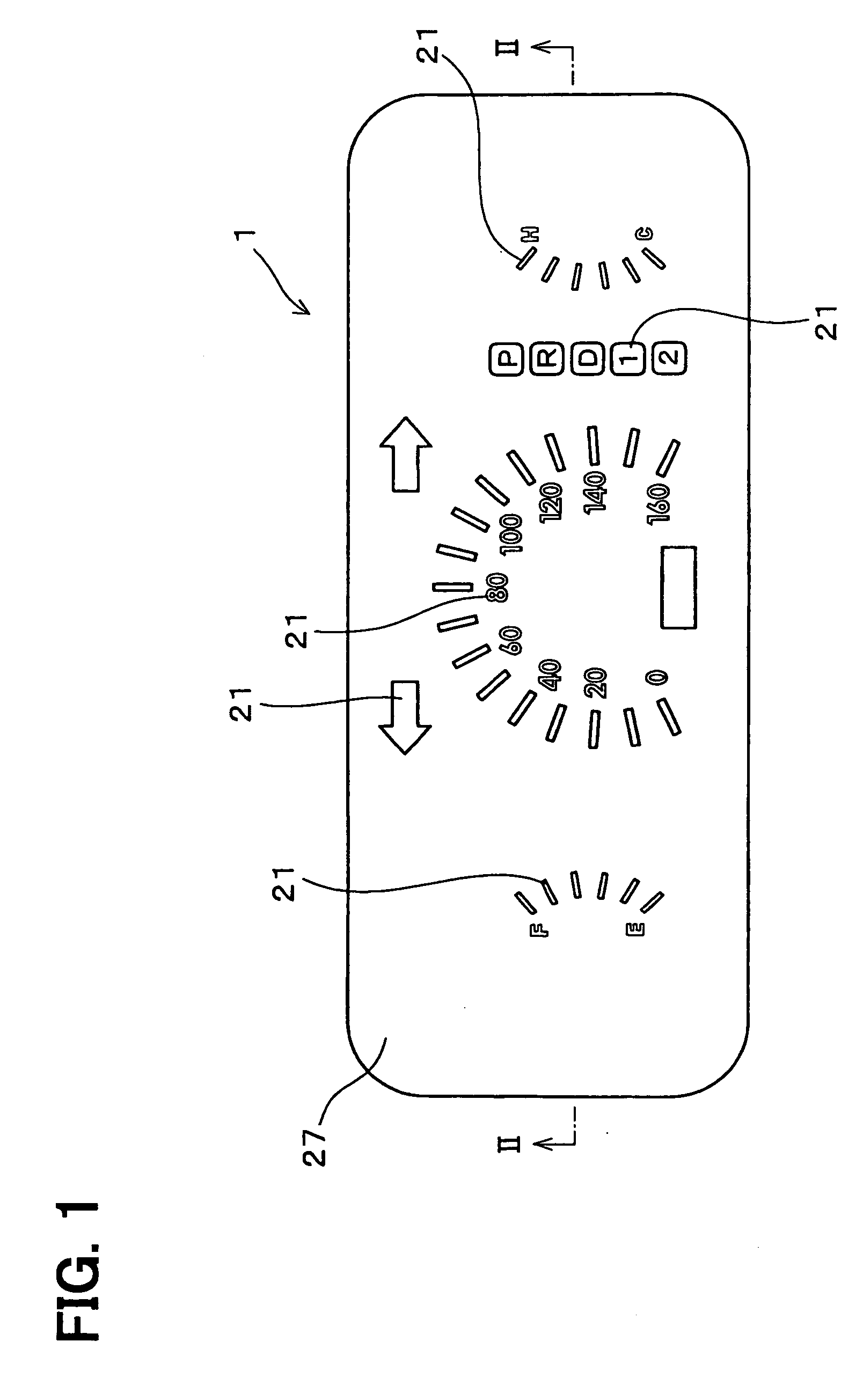
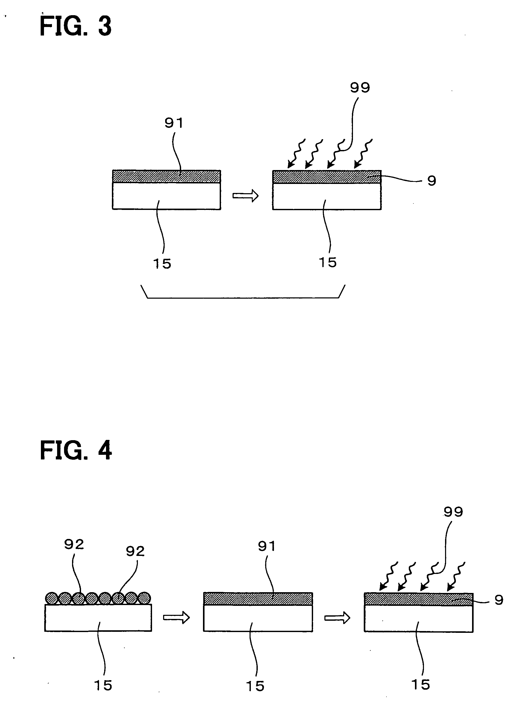
[0034] A formed indicator panel 1 in an embodiment shown in FIGS. 1, 2 is shaped by thermoforming an indicator panel portion 19 shown in FIG. 13. The indicator panel portion 19 includes a resin substrate 15 and an inkjet design film 2 on the substrate 15. The design film 2 is formed by printing a UV hardening ink in an inkjet printing, and hardening.

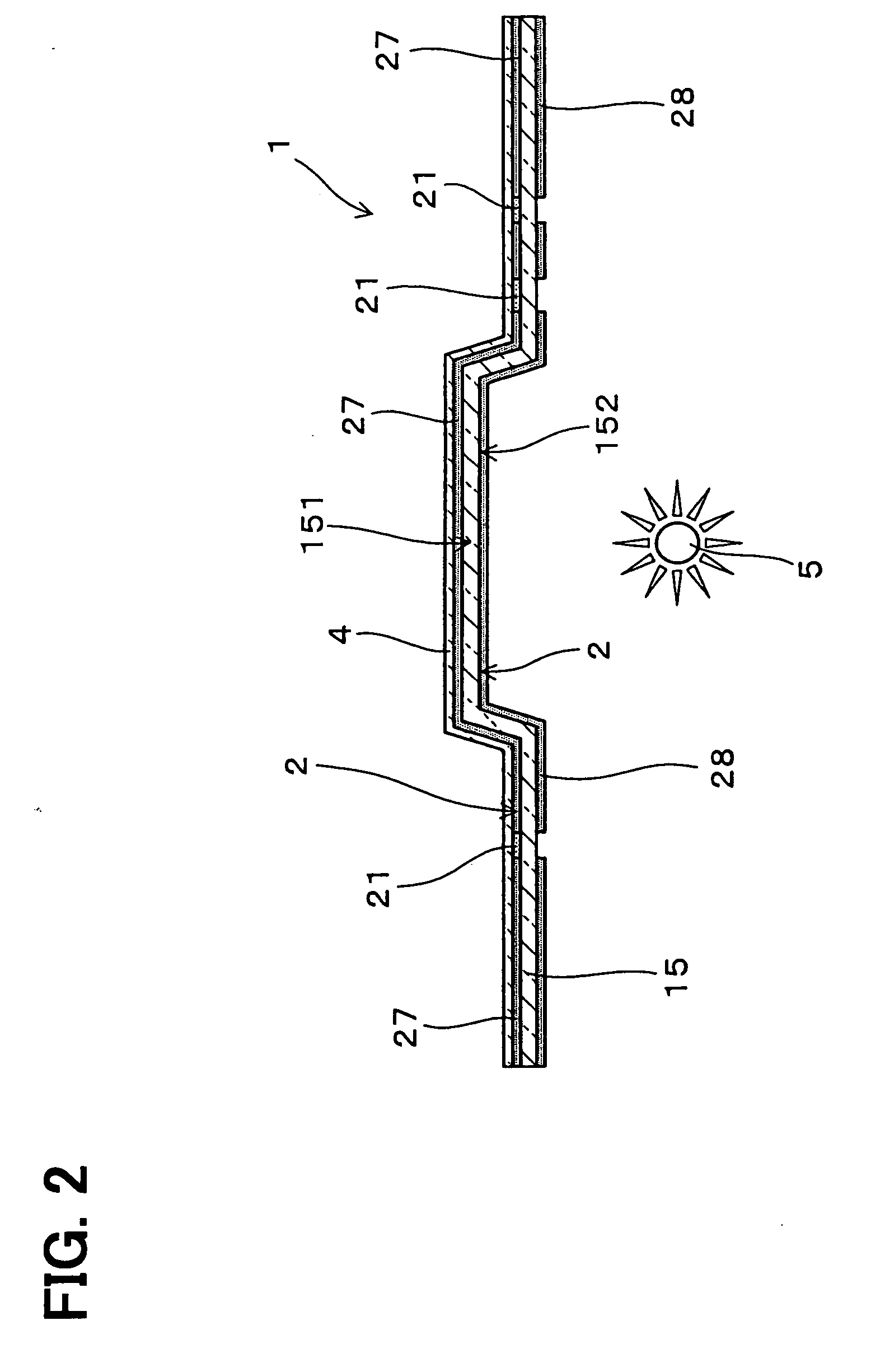
[0035] As shown in FIGS. 1, 2, the shaped indicator panel 1 can be used for a meter dial for an automobile instrument device (display device) in this embodiment. The panel 1 includes the translucent resin substrate 15 and the inkjet design film 2. The film 2 is layered on a design face 151 of the substrate 15. The film 2 is made of the UV hardening ink or a mixture of the inks. For example, the inks are colored in clear (transparent), black, white, magenta, cyan, yellow, light cyan and light magenta.

[0036] In the panel 1, a translucent portion 21 and an opaque portion 27 are formed. When a light is illuminated to a back face 152 of the...


PUM

PropertyMeasurementUnit
Lengthaaaaaaaaaa
Fractionaaaaaaaaaa
Fractionaaaaaaaaaa

Abstract

An indicator panel is shaped by thermoforming an indicator panel. The indicator panel includes a resin substrate and an inkjet design film on the substrate. The design film is formed by printing a UV hardening ink in an inkjet printing, and hardening. A crack and a removal of the design film can be decreased such that the formed indicator panel can have a high-quality design.

Description

CROSS REFERENCE TO RELATED APPLICATION [0001] This application is based on Japanese Patent Application No. 2005-281674 filed on Sep. 28, 2005, the disclosure of which is incorporated herein by reference in its entirety. BACKGROUND OF THE INVENTION [0002] 1. Field of the Invention [0003] The present invention relates to an indicator panel having an inkjet design film on a resin substrate, and a method of manufacturing the indicator panel. [0004] 2. Description of Related Art [0005] Conventionally, an indicator device, e.g., an instrument panel, is provided in a vehicle. Generally, the indicator device includes a panel and a light source. The panel includes a design portion having scales and letters, and the light source is provided at a backside of the panel. In the panel, the design portion except for the scales and the letters is made of an opaque portion, in which a light is not transmitted. The scales and the letters are made of a translucent portion, in which a light is transmit...

Claims


Application Information

Patent Timeline
IPC IPC(8): B41M5/00
CPCB41M5/0011B29C2795/002B41M5/0064B41M5/50B41M7/0072B41M7/0081Y10T428/24777Y10T428/24521Y10T428/24529Y10T428/24802Y10T428/24479B29L2031/3008B29C47/0019B29C47/0054B29C51/02B60K37/02B41M5/0047B29C48/0017B29C48/07
Inventor MIGITAKA, YUKINORIIWASE, TERUHIKOKATO, KAZUOAOKI, TAKASHI
Owner DENSO CORP
Why Eureka
Try Eureka