In-mold forming apparatus, in-mold forming method, in-mold formed article manufacturing method, and dust collector

a technology of in-mold forming and in-mold forming, which is applied in the direction of auxillary shaping apparatus, chemistry apparatus and processes, manufacturing tools, etc., can solve the problems of increasing the manufacturing cost, affecting the quality of the finished product, so as to prevent the occurrence of defective articles, reduce the production cost, and reduce the production cost

Inactive Publication Date: 2006-04-20
KK TOSHIBA
View PDF3 Cites 2 Cited by
  • Summary
  • Abstract
  • Description
  • Claims
  • Application Information

AI Technical Summary

Benefits of technology

[0021] According to the present invention, an occurrence of defective articles is prevented and a high resolution pattern or design can be efficiently transferred to the outer surface of each formed article. Further, fine dust can be collected efficiently.

Problems solved by technology

The in-mold forming method aforementioned causes the following problem.
Further, when the dent is not found and the foil dust P is not wiped out, there is a fear of continuous manufacture of defective articles.
Particularly, in the display unit of the sub-liquid crystal panel of a portable telephone and so on, the parts are transparent, so that the failure rate due to the dent is high, and the yield rate of some part is low such as 50% to 60%, and thereby an increase in the manufacturing cost is caused.

Method used


Image

  • In-mold forming apparatus, in-mold forming method, in-mold formed article manufacturing method, and dust collector
  • In-mold forming apparatus, in-mold forming method, in-mold formed article manufacturing method, and dust collector
  • In-mold forming apparatus, in-mold forming method, in-mold formed article manufacturing method, and dust collector

Examples


first embodiment

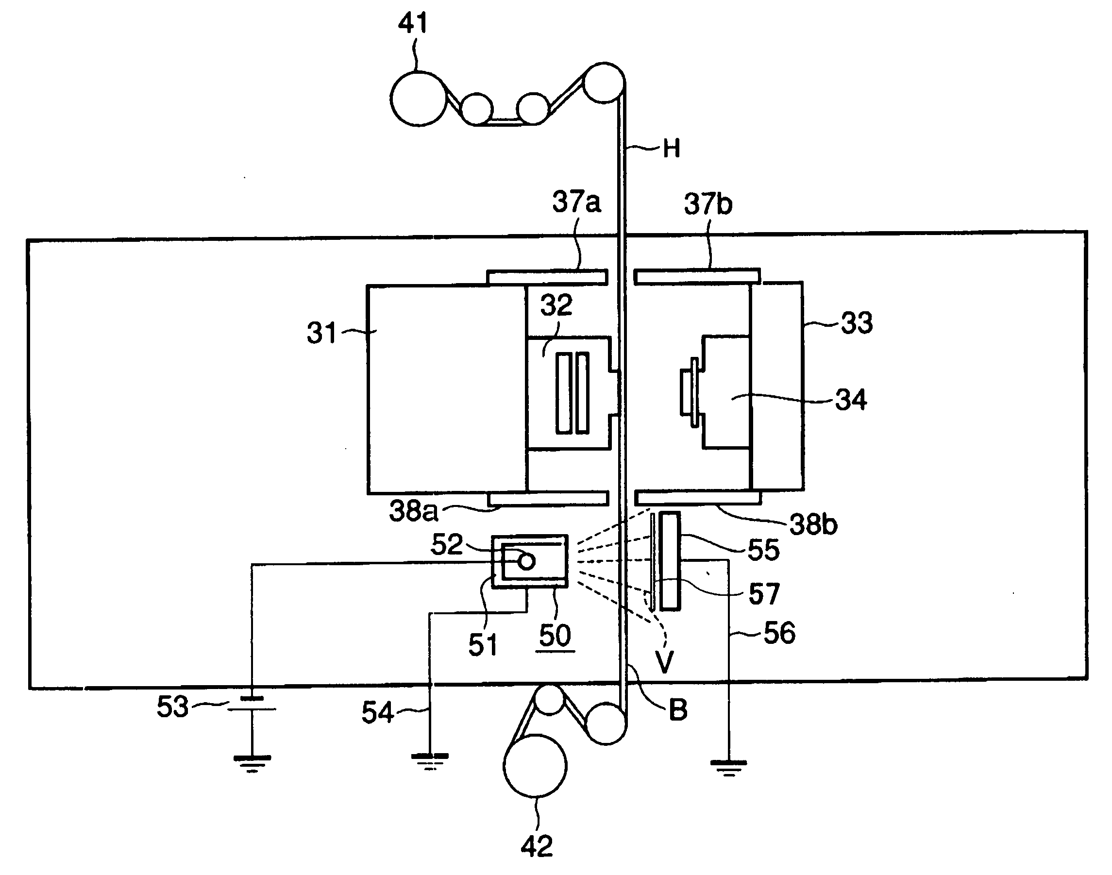
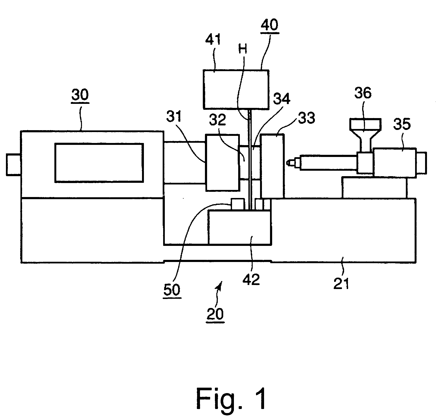
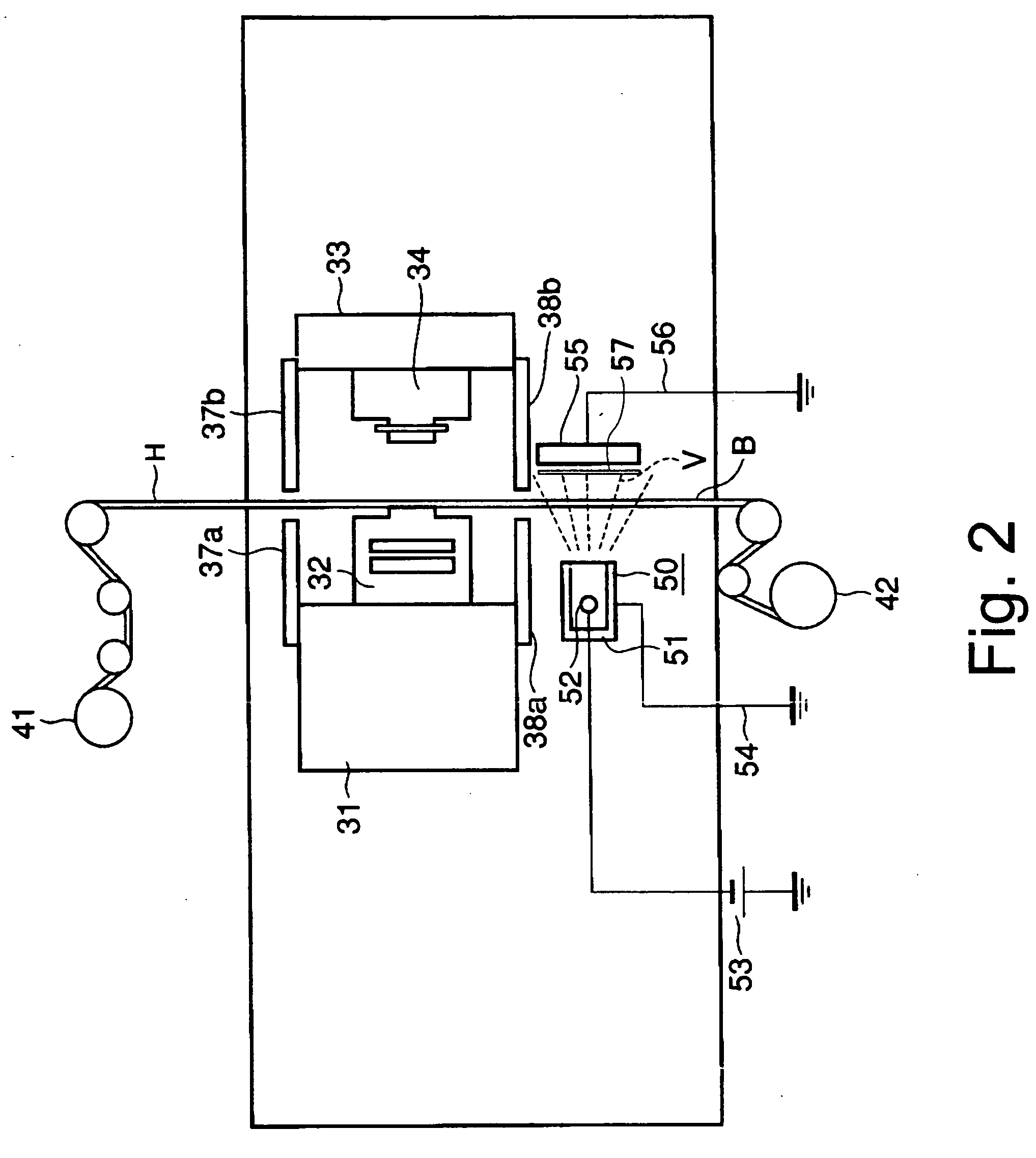
[0039]FIG. 1 is a front view showing an in-mold forming apparatus 20 according to a first embodiment of the present invention, FIG. 2 is a schematic view showing an essential part of the in-mold forming apparatus 20, and FIG. 3 is a front view showing an in-mold foil H used in the in-mold forming apparatus 20. FIGS. 4 and 5 are cross sectional views of the in-mold foil H cut off along a line X-X shown in FIG. 3 viewed in a direction of an arrow, respectively, and FIG. 6 is an illustration for showing an operation principle of the in-mold forming apparatus 20. FIGS. 7 to 9 are cross sectional views showing an injection forming step by the in-mold forming apparatus 20, respectively. Further, in these drawings, numeral H indicates the in-mold foil, B the base film, F a transfer foil, and P the foil dust.

[0040] As shown in FIG. 1, the in-mold forming apparatus 20 is provided with a frame 21 loaded on the floor, an injection forming mechanism 30 installed on the frame 21, an in-mold foi...

second embodiment

[0054]FIG. 10 is a perspective view schematically showing an in-mold forming apparatus 60 according to a second embodiment of the present invention. In FIG. 10, to the same functional parts as those shown in FIG. 2, the same numerals are assigned, and the detailed explanation thereof will be omitted.

[0055] In the in-mold forming apparatus 20 according to the first embodiment aforementioned, the charger 50 is installed only on the side of the foil winding machine 42 viewed from the cavity-side mold 32 and core-side mold 34. However, in the in-mold forming apparatus 60 according to this embodiment, the chargers 50 are additionally installed on the side of the foil sender 41 and on the cavity-side mold 32 and core-side mold 34. Further, the charger body 51 and the plate electrode 55 are installed in the symmetrical positions with respect to the in-mold foil H.

[0056] Also in the in-mold forming apparatus 60 structured like this, the same effects as those of the in-mold forming apparat...

third embodiment

[0057]FIG. 11 is a perspective view schematically showing an in-mold forming apparatus 70 according to a third embodiment of the present invention. In FIG. 11, to the same functional parts as those shown in FIGS. 2 and 10, the same numerals are assigned and the detailed explanation thereof will be omitted.

[0058] In the in-mold forming apparatus 20 according to the first embodiment aforementioned and the in-mold forming apparatus 60 according to the second embodiment aforementioned, the in-mold foil feeding mechanism 40 is installed only in the vertical direction. However, in the in-mold forming apparatus 70 according to this embodiment, the in-mold foil feeding mechanisms 40 are arranged in the vertical and horizontal directions one by one. Therefore, in the in-mold forming apparatus 70, composite in-mold forming in which the in-mold foils H are arranged in the vertical direction and horizontal direction can be executed.

[0059] Further, the chargers 50 are installed in the position...


PUM

PropertyMeasurementUnit
yield rateaaaaaaaaaa
thicknessaaaaaaaaaa
voltageaaaaaaaaaa

Abstract

An in-mold forming apparatus including a first mold and a second mold for injection molding and a film feeding mechanism for feeding in-mold foil between the first mold and the second mold. A transfer foil is formed on the in-mold foil. The in-mold forming apparatus further includes a mold closing mechanism for closing the first mold and the second mold, thereby to fix the in-mold foil inside a cavity formed between the first mold and the second mold, a resin injection forming mechanism for injecting fused resin into the cavity, thereby to unit the transfer foil formed on the in-mold foil with the resin, and a charger arranged in the neighborhood of at least one of the first mold, the second mold, and the in-mold foil. The charger includes a charging unit for freeing ions and charging particles in the neighborhood of the in-mold foil, and an electrode for adsorbing the particles charged by the ions.

Description

CROSS-REFERENCE TO RELATED APPLICATIONS [0001] This application is based upon and claims the benefit of priority from the prior Japanese Patent Application No. 2004-306161, filed on Oct. 20, 2004; the entire contents of which are incorporated herein by reference. BACKGROUND OF THE INVENTION [0002] 1. Field of the Invention [0003] The present invention relates to an in-mold forming apparatus, an in-mold forming method and an in-mold formed article manufacturing method, and more particularly relates to an in-mold forming apparatus, an in-mold forming method and an in-mold formed article manufacturing method for forming resin parts used for portable telephones, mobile information terminal devices, note-type personal computers, household electric appliances, car parts, and so on. Also, the present invention relates to a dust collector, and more particularly to a dust collector for efficiently collecting dust. [0004] 2. Description of the Background [0005] Conventionally, resin is inject...

Claims


Application Information

Patent Timeline
Patent Type & Authority Applications(United States)
IPC IPC(8): B29C45/14
CPCB03C3/017B08B6/00B29C45/14016B29C45/14827B29C45/1701
Inventor KAIRIKU, YOSHINORIKOIKE, NOBORU
Owner KK TOSHIBA
Why Eureka
Try Eureka