Peel-away sheath

a sheath and a needle technology, applied in the direction of catheters, intravenous devices, guide needles, etc., can solve the problems of kinking of the sheath, difficulty in routing the sheath through the vasculature, and difficulty in transferring torsional loads through the sheath

Inactive Publication Date: 2005-09-06
CARDIAC PACEMAKERS INC
View PDF22 Cites 148 Cited by
  • Summary
  • Abstract
  • Description
  • Claims
  • Application Information

AI Technical Summary

Benefits of technology

[0022]In a further detailed aspect, the nut device is positioned on the tube with the hub positioned within the second lumen. The seal is positioned on the tube, proximal to the hub of the tube. The screw device is positioned on the guide sheath, proximal to the seal with the threaded portion of the screw device positioned at a distal portion of the screw device. Also, the nut device and the screw device are screwed together, thereby causing the nut device to push the hub into a distal end of the seal and the screw device to push into a proximal end of the seal. This causes the lumen of the seal to become smaller and to form a friction grip with the guide sheath.

Problems solved by technology

Although the longitudinal slits, grooves and perforations of current peel-away sheaths promote easy splitting of the sheaths, they also predispose the sheaths to kinking along the thinner cross sections thereby created.
The longitudinal slits, grooves and perforations also make it difficult to transfer torsional loads through the sheaths.
Kinking of the sheath and poor torque transfer throughout the length of the sheath cause difficulties in routing the sheath through the vasculature.

Method used


Image

  • Peel-away sheath
  • Peel-away sheath
  • Peel-away sheath

Examples


Embodiment Construction

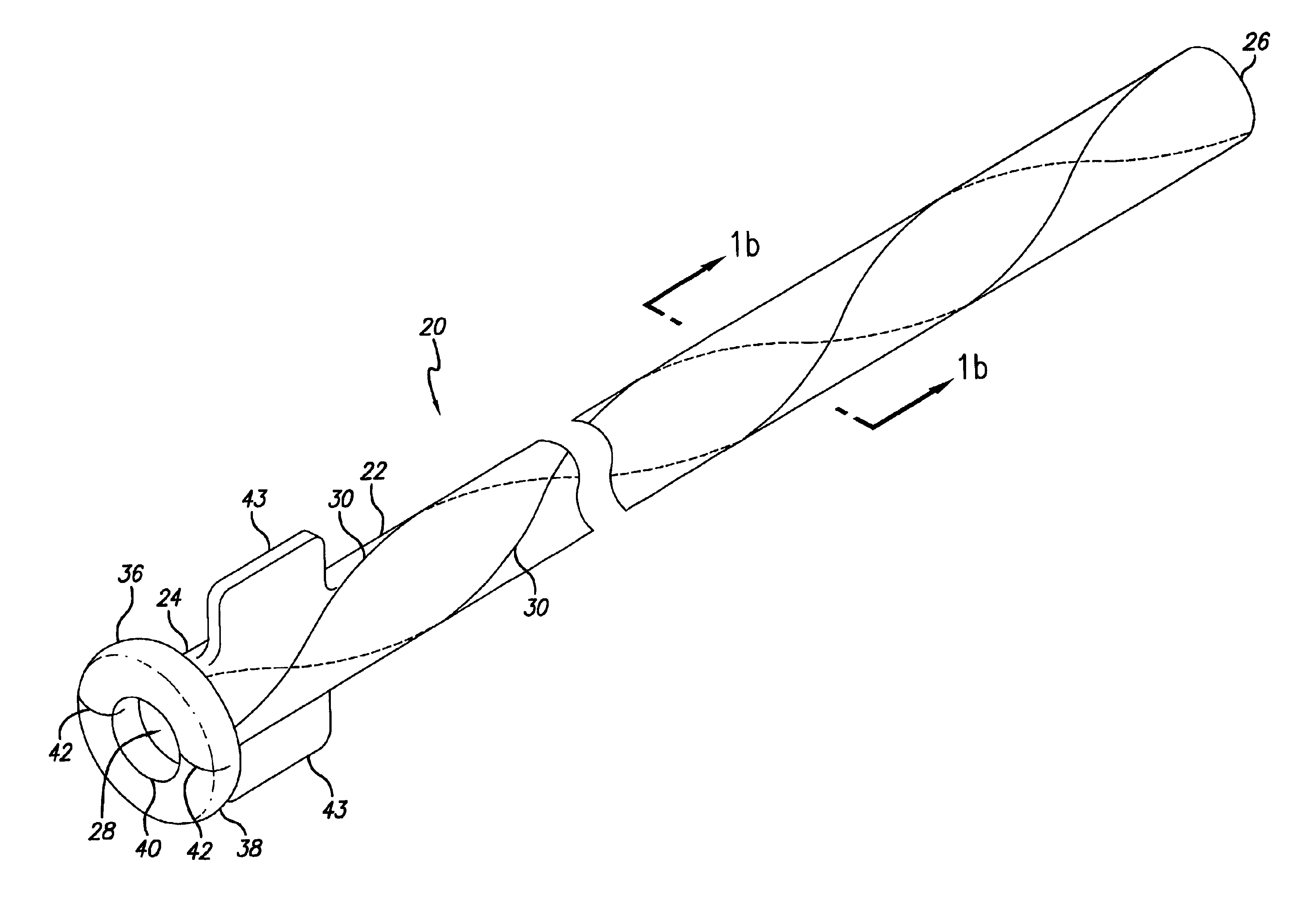
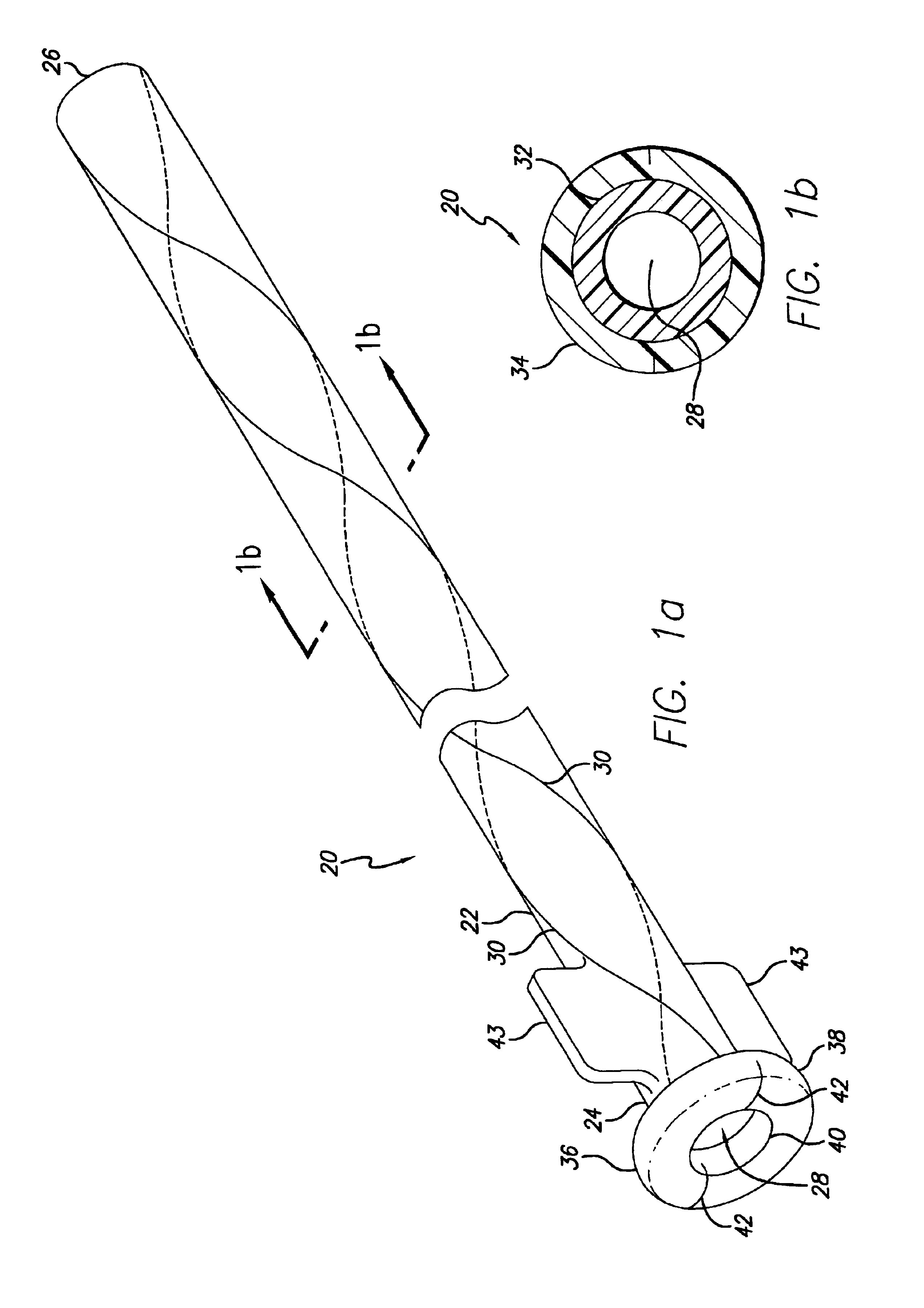
[0047]Referring now to the drawings, wherein the reference numerals denote like or corresponding parts throughout the figures, and particularly to FIG. 1a, there is shown a longitudinal catheter sheath 20 including an elongate tube 22 having a proximal end 24, a distal end 26 and a lumen 28 throughout its length. The sheath 20 also includes at least one weakened area 30 which extends along the length of the sheath in a non-longitudinal pattern which facilitates peeling of the sheath. (FIG. 1a depicts two weakened areas arranged in a helical pattern.)

[0048]With reference to FIG. 1b, which is a cross-sectional view taken from FIG. 1a, the sheath 20 may include a layered composite. As depicted in this embodiment, the inner layer 32 may be a hollow tube made of a polymer possessing a high modulus of elasticity, such as polyetheretherketone (PEEK). The outer layer 34 may be made of a flexible, intermediate-durometer polymer such as polyether block amide, known commercially as Pebax™. In ...


PUM


Abstract

A peel-away sheath for a catheter includes at least one weakened area in a non-longitudinal pattern, such as a helical pattern, along the length of the sheath. One embodiment of a catheter sheath includes a tube having at least one pull wire integrally located within its wall. Another embodiment of a catheter sheath includes a tube having at least one integral lumen within its wall. The integral lumen may house a filling material. One embodiment of a catheter may include a first sheath which is positioned within a second sheath, with each of the first and second sheaths having at least one weakened area along its length. A reinforcing guide for a guide catheter includes a tube having a lumen with a diameter at least as large as the guide catheter diameter. The reinforcing guide includes a gap with a width which is less than the guide catheter diameter.

Description

BACKGROUND OF THE INVENTION[0001]1. Field of the Invention[0002]The invention relates generally to delivery systems for interventional devices and, more particularly, to a guiding catheter for delivering an interventional device to an anatomical site.[0003]2. Description of the Related Art[0004]Numerous devices and procedures have been developed for delivering interventional devices to a work site within an anatomical body. Such procedures usually involve the percutaneous introduction of an interventional device into the lumen of an artery, usually through a catheter. Some prior art devices for delivering an interventional device utilize a guiding catheter. The guiding catheter is routed through the vasculature of the anatomical body to a location proximate the work site. The interventional device which is coupled to a delivery device, such as a guide wire, is then routed through the guiding catheter and to the work site. After the interventional device is positioned at the work sit...

Claims


Application Information

Patent Timeline
Patent Type & Authority Patents(United States)
IPC IPC(8): A61M25/06
CPCA61M25/0668
Inventor HALL, JEFFREY A.BOWE, WADE A.TOCKMAN, BRUCE A.WESTLUND, RANDY W.BECKER, NEIL
Owner CARDIAC PACEMAKERS INC
Why Eureka
Try Eureka