
Method and apparatus for signal searching

a signal and apparatus technology, applied in the direction of electrical equipment, transmission, transmission monitoring, etc., can solve the problems of increased design and processing costs associated, so as to achieve large mean acquisition time (mat), increase design and processing costs, and wide

Inactive Publication Date: 2013-10-22
MASSACHUSETTS INST OF TECH
View PDF14 Cites 1 Cited by
  • Summary
  • Abstract
  • Description
  • Claims
  • Application Information

AI Technical Summary

Benefits of technology

The present invention provides a searching apparatus and method for reducing the Mean Acquisition Time (MAT) and design and processing costs associated with acquiring wide or ultra bandwidth signals. One approach is to improve the MAT at the detection layer by increasing the resources dedicated to forming a decision variable. The other approach is to improve the MAT at the search layer by using a search pattern, such as an expanding zigzag window, a non-consecutive or consecutive serial search, a fixed-step serial search, or a bit-reversal search. However, these searching methods still result in high costs. The present invention presents a searching apparatus and method that reduces the MAT by selectively choosing a range of bins from a preset list of bins, comparing a local signal with a received signal, and assigning weightings to the bins if the signals do not match. This approach reduces the cost and complexity of the acquisition process.

Problems solved by technology

Acquisition of wide or ultra bandwidth signals is a challenging task.
The use of a wide transmission bandwidth typically translates into a large mean acquisition time (MAT).
A large MAT may increase design and processing costs associated with the acquisition.
However, these searching methods still yield high design and processing costs.

Method used


Image

  • Method and apparatus for signal searching
  • Method and apparatus for signal searching
  • Method and apparatus for signal searching

Examples


Embodiment Construction

[0018]A description of example embodiments of the invention follows.

[0019]In example embodiments of the present invention, techniques for searching for one or more targets are presented. In terms of wireless communications, the target may be a received signal, and the description below is presented in that example context. However, it should be understood that the example embodiments may be applied to technologies other than wireless communications.

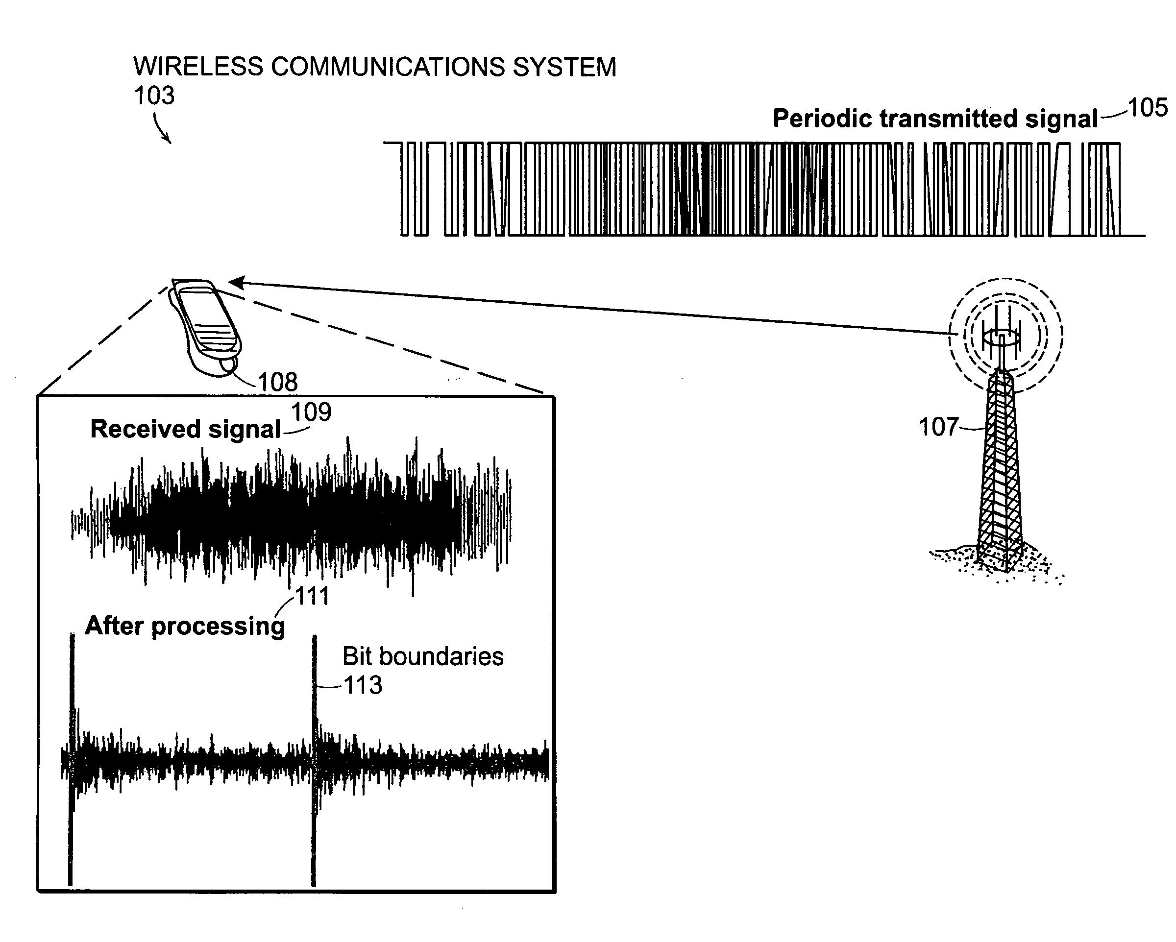
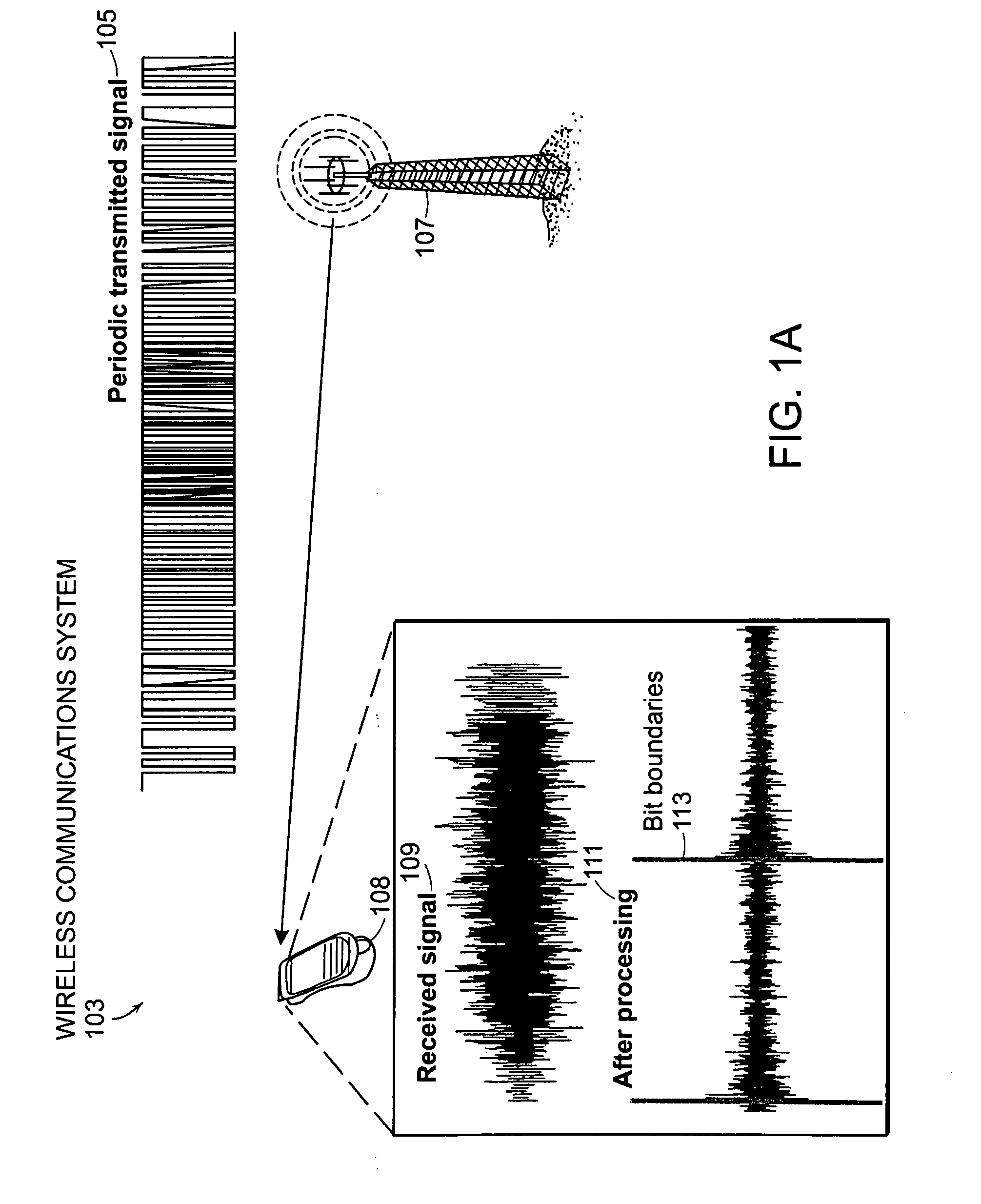
[0020]FIG. 1A illustrates an example of a wireless communications system 103. A periodic signal 105 may be sent to a receiver with the use of a transmitter. In the present example, the receiver is a cell phone 108, and the transmitter is a base station 107. Due to noise, dispersion, and / or interference, for example, the receiver 108 may receive multiple reflected copies of the transmitted signal 109 due to multi-path, for example, with each copy being an attenuated version of the original transmitted signal shifted in time or phase. There...


PUM


Abstract

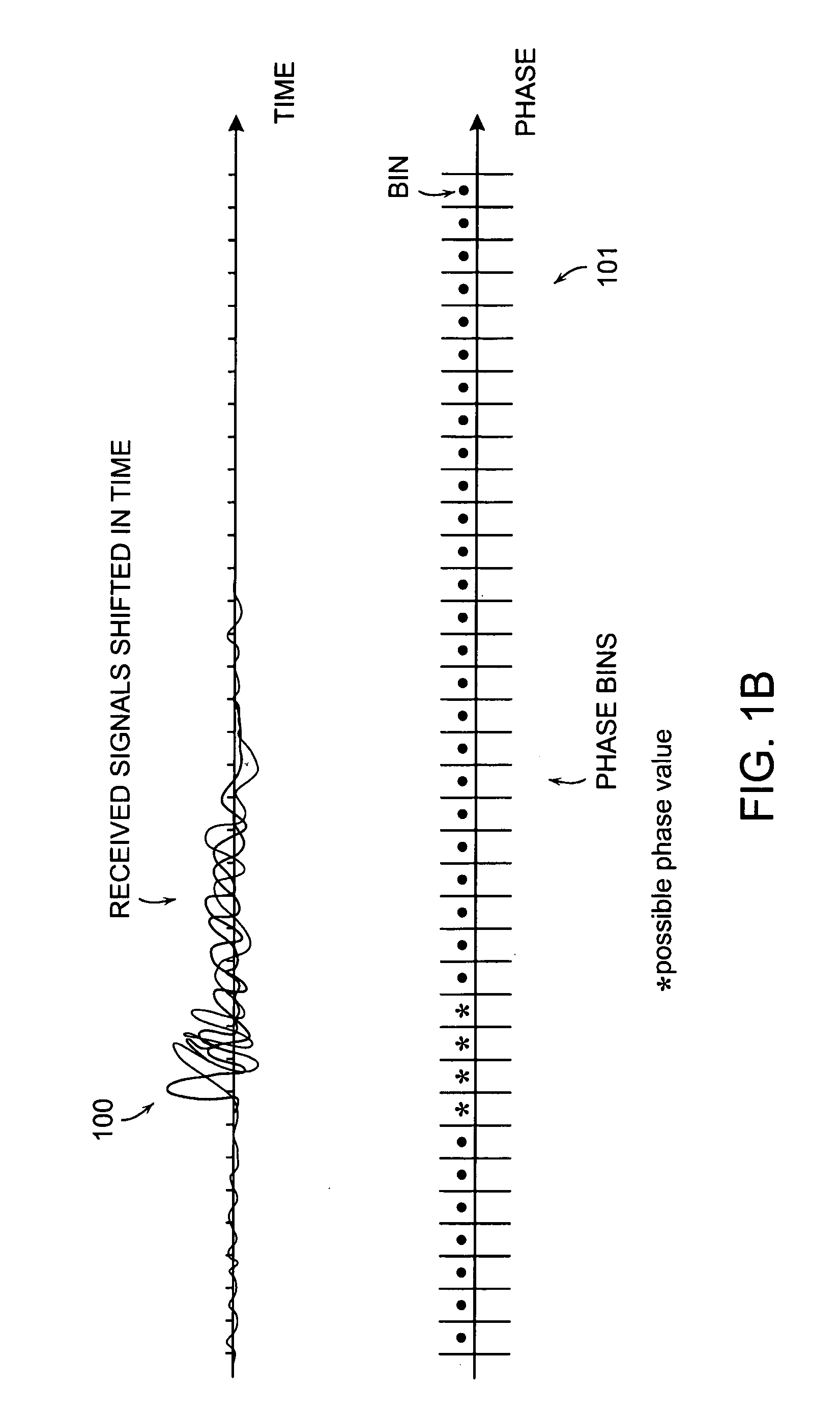
A method and corresponding apparatus for searching for a signal is presented. The apparatus may be configured to select a first bin within a range of bins characterizing an uncertainty region. The bins may represent a phase within a bandwidth of interest. The apparatus may also be configured to compare a local signal, having a phase corresponding to the first bin, with a received signal, the received signal being received via a transmission medium. The apparatus may report whether the local signal matches the received signal. The apparatus may assign weightings to the bins if the local signal does not match the received signal. If a match is not found, the apparatus may select a next bin according to the weightings or according to characteristic of the transmission medium until a matching bin is obtained. One benefit of the search is reduced search time to allow, for example, a cell phone to synchronize the phase of a received signal more quickly than is currently done.

Description

RELATED APPLICATIONS[0001]This application claims the benefit of U.S. Provisional Application No. 60 / 857,810, filed on Nov. 8, 2006. The entire teachings of the above applications are incorporated herein by reference.GOVERNMENT SUPPORT[0002]The invention was supported, in whole or in part, by a grant N00014-03-1-0489 from the Office Of Naval Research. The Government has certain rights in the invention.BACKGROUND OF THE INVENTION[0003]There has been considerable interest in the use of ultrawide bandwidth (UWB) systems for both commercial and military applications. UWB may be used to refer to any radio technology having bandwidth exceeding the lesser of 500 MHz or 20% of the arithmetic center frequency, according to Federal Communications Commission (FCC). The use of large transmission bandwidth translates to many advantages over the conventional narrowband systems. To realize these advantages, however, the receiver may need to perform signal acquisition.[0004]Signal acquisition may i...

Claims


Application Information

Patent Timeline
Patent Type & Authority Patents(United States)
IPC IPC(8): H04B17/00
CPCH04B1/7183
Inventor SUWANSANTISUK, WATCHARAPANWIN, MOE Z.
Owner MASSACHUSETTS INST OF TECH
Learn More