Bollard lamp

a technology of boltards and lamps, applied in the field of boltard lamps, can solve the problems of increasing the number of bollards required for any given design, requiring unnecessary space on the path, etc., and achieve the effect of improving illumination

Active Publication Date: 2007-04-05
ABL IP HLDG
View PDF11 Cites 23 Cited by
  • Summary
  • Abstract
  • Description
  • Claims
  • Application Information

AI Technical Summary

Problems solved by technology

This typically requires unnecessary space for the path.
Naturally, this adds to the number of bollards required for any given design.

Method used


Image

  • Bollard lamp
  • Bollard lamp
  • Bollard lamp

Examples


first embodiment

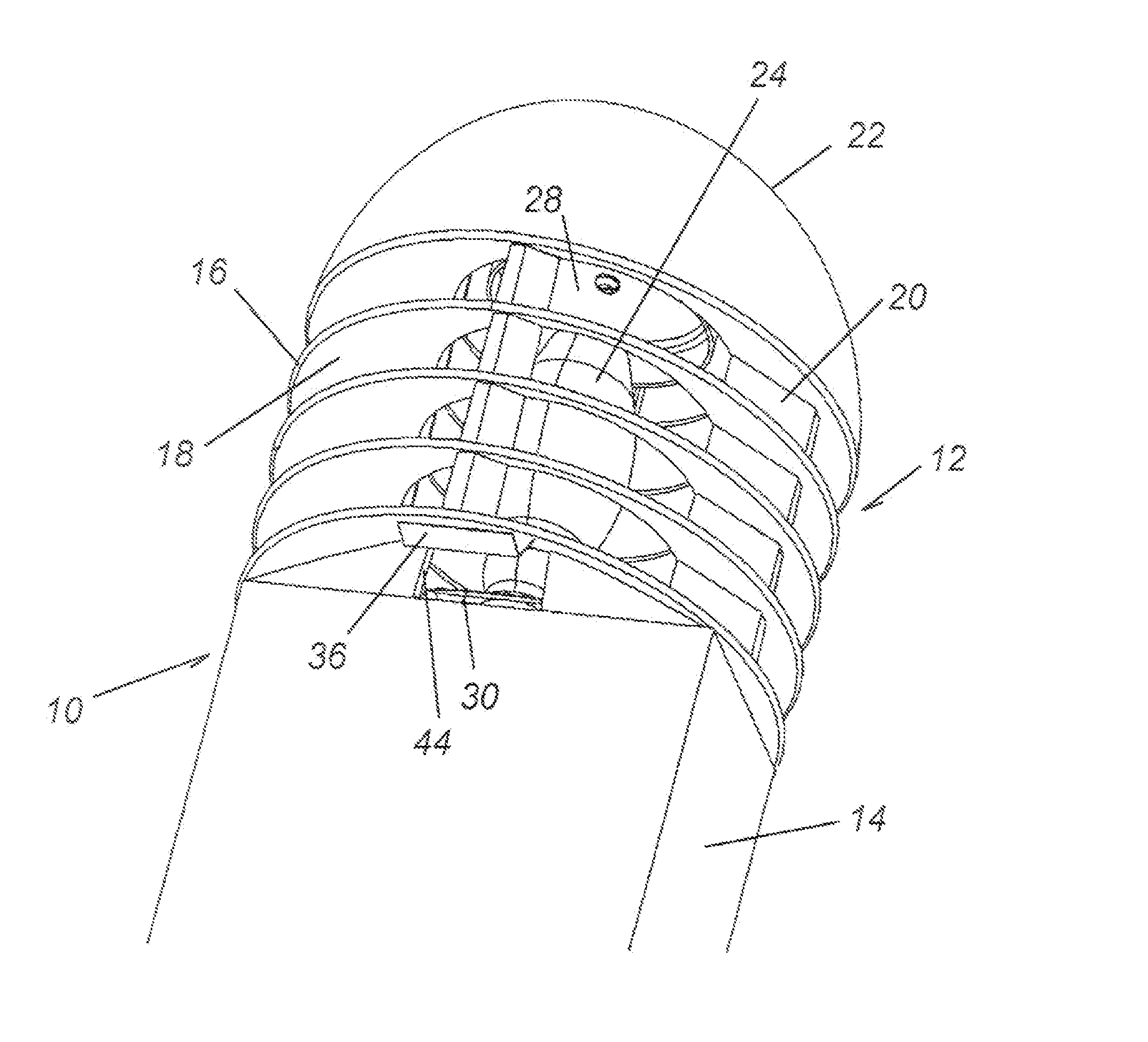
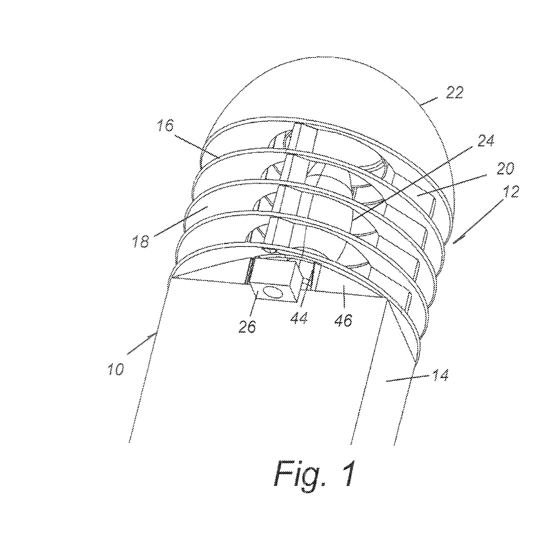
[0015]FIG. 1 illustrates a first embodiment employing a bollard 10 of rectangular cross section. A lamp, generally designated 12, sits atop the bollard post 14. The lamp 12 is made up of what is commonly referred to as a louver stack 16 composed of a plurality of louvers 18 which are spaced apart in the longitudinal direction of the bollard post 14 and supported by vertical elements 20. A dome 22 provides an opaque cap for the lamp 12. The louver stack 16 is shown to be cylindrical in shape but may be of other shapes including hemicylindrical if employed against a wall.

[0016] Located within the center of the louver stack 16 is a primary light source 24. The light source 24 is shown to be a bulb.

[0017] The louvers 18 extend outwardly past the periphery of the top end of the bollard post 14 at least in one segment. Below the umbrella of the lowermost louver 18 which is most adjacent the top of the bollard post 14, an LED module 26 defines a down light means for directing light downwa...

second embodiment

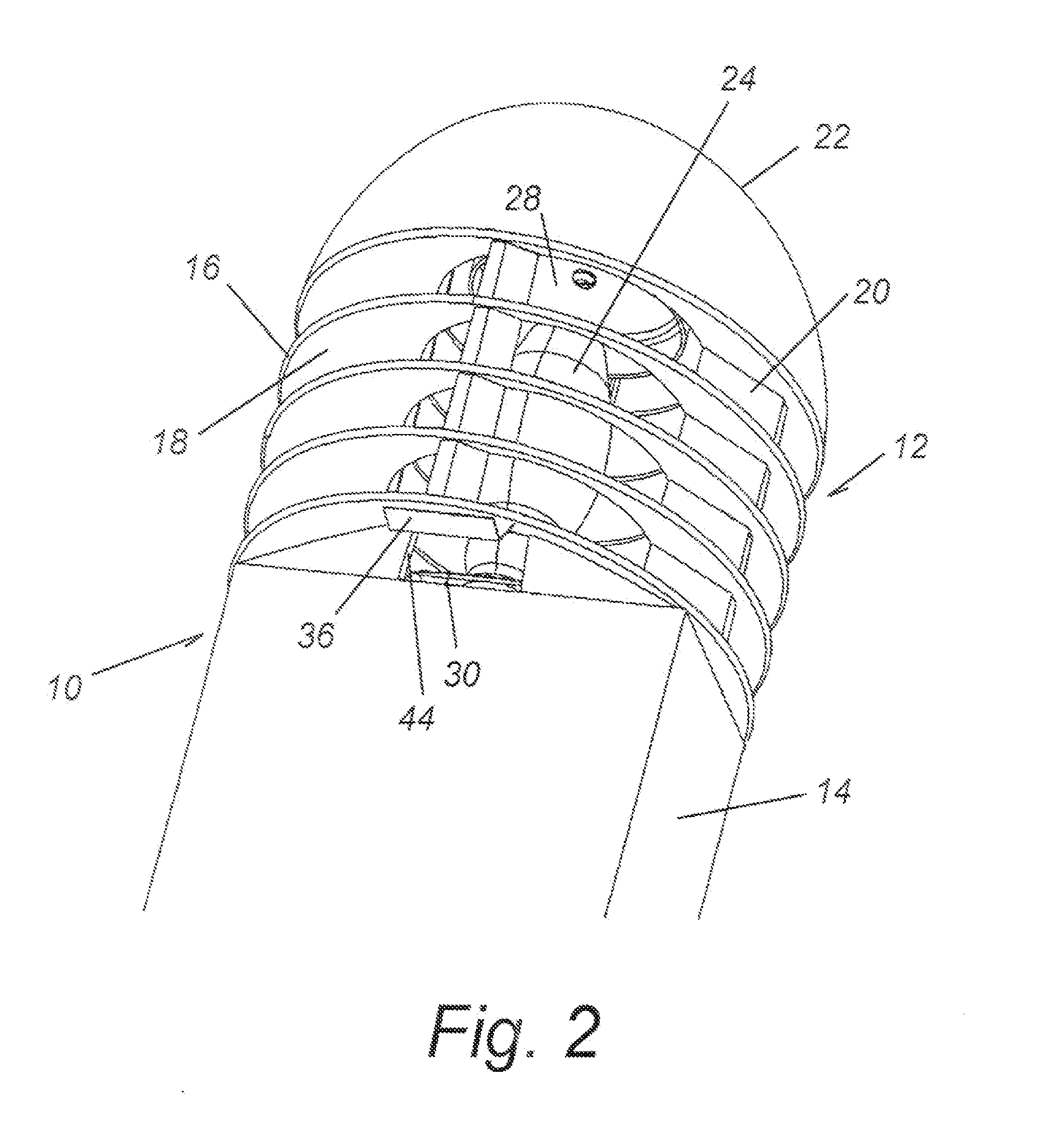
[0018]FIGS. 2, 3 and 4 illustrate the present invention. The basic structures of the bollard post 14, louvered stack 16 with its louvers 18 and the dome 22 are the same. A primary light source 24 is also similarly positioned.

[0019] To achieve a down light means for directing light downwardly about the base end of the bollard post 14, a top reflector 28 is located above the primary light source 24. This top reflector 28 receives light from the primary light source 24 and directs that reflected light downwardly about the primary light source 24 to a bottom reflector 30. The bottom reflector 30, as can be seen in FIG. 4, is inclined to receive light from the top reflector 28 and direct that light outwardly toward the louver 18 which is the bottom most louver and most adjacent the bollard post 14. In this embodiment, there are two reflective surfaces 32, 34 defining the bottom reflector 30. Thus, in this embodiment, light is directed outwardly in two directions. These directions are tow...


PUM


Abstract

A bollard includes a bollard post having a lamp which includes a louver stack. The louver stack includes louvers spaced apart in the longitudinal direction of the bollard post. The bollard post is rectangular in cross section and the louver stack extends outwardly beyond the periphery of the bollard. There is a primary light source inwardly of the louver stack and a mechanism for providing light downwardly about the base end of the bollard post. One such mechanism includes an LED providing a light wash down the bollard post from beneath where that louver extends outwardly of the periphery of the bollard post. A second mechanism employs a top reflector above the primary light source to reflect light downwardly about the light source. Bottom reflector surfaces direct the light from the top reflector outwardly to louver reflectors located beneath the lowermost louver. Such reflectors can reflect light downwardly for light wash of the bollard post and an illumination about the base of the bollard post. The spacing between the lowermost louver and the periphery of the bollard post is exposed to the primary light source to create additional light downwardly to about the bollard post.

Description

BACKGROUND OF THE INVENTION [0001] This is a divisional of U.S. application Ser. No. 11 / 213,343, filed Aug. 25, 2005, the disclosure of which is incorporated herein by reference.BACKGROUND OF THE INVENTION [0002] The field of the present invention is bollard lighting. [0003] Traditional stacked louvered bollards with a single light source centered within a louver stack atop the bollard have a dark spot or shadow around the base of the bollard. The louvers typically extend to the outside edge of the base and direct light away from the bollard and immediate surrounding area. [0004] The shadow around the base of traditional stacked louvered bollard lamps prevents the area close to the bollard from being illuminated. Because of this, such bollards are typically displaced from paths and the like in order to achieve appropriate illumination of such paths. This typically requires unnecessary space for the path. Alternatively, the illumination for an area can rely on overlapping areas of il...

Claims


Application Information

Patent Timeline
Patent Type & Authority Applications(United States)
IPC IPC(8): F21S13/10F21S8/00
CPCE01F9/0165F21S8/083F21V7/0025F21V11/02F21W2111/00F21W2111/02F21W2131/10F21Y2101/02F21Y2113/02E01F9/617F21Y2113/20F21Y2115/10
Inventor LEONHARDT, MICHAEL P.POPPENHEIMER, TORI C.CROOKHAM, DAVIDSKOGG, NICOLE
Owner ABL IP HLDG
Why Eureka
Try Eureka