Door striker

a door and latch technology, applied in the field of door strikers, can solve the problems of generating noise that distracts the driver of the automobile, damage the latch assembly,

Inactive Publication Date: 2007-05-24
ILLINOIS TOOL WORKS INC
View PDF7 Cites 24 Cited by
  • Summary
  • Abstract
  • Description
  • Claims
  • Application Information

AI Technical Summary

Benefits of technology

[0012]FIG. 2 illustrates an isometric view of a conventional automobile door striker.
[00

Problems solved by technology

This shaking and rattling can damage the latch assembly and

Method used


Image

  • Door striker
  • Door striker
  • Door striker

Examples


Embodiment Construction

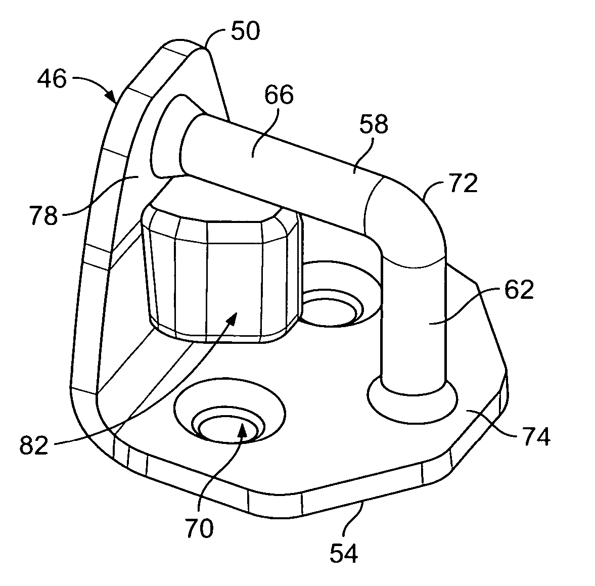
[0022]FIG. 5 illustrates an isometric view of a door striker 46 according to an embodiment of the present invention. The door striker 46 includes a generally triangular back plate 50 formed with, and extending generally perpendicularly from, a base plate 54. The door striker 46 includes an L-shaped cylindrical bar 58 that extends between the back plate 50 and base plate 54. The bar 58 includes a rear section 62 and a top section 66 that are generally perpendicular to each other and formed together at an elbow 72. The rear section is formed with, and extends from, a top surface 74 of the base plate 54, and the top section 66 is formed with, and extends from, a front surface 78 of the back plate 50. By way of example only, the back plate 50, base plate 54, and bar 58 may be made of metal. The base plate 54 includes holes 70 that are configured to receive fasteners configured to secure the base plate 54 to a base in the door frame of an automobile such that the door striker 46 is posit...


PUM


Abstract

A door striker for use with an automobile door latching assembly having a latch positioned within a gap defined by an edge. The door striker includes a bar configured to be securably engaged by the latch of the latching assembly and a bumper positioned proximate the bar and configured to be received within the gap of the latching assembly to resistably engage the edge of the gap when the latching assembly moves with respect to the bar.

Description

RELATED APPLICATIONS [0001] This application relates to and claims priority benefits from U.S. Provisional Patent Application No. 60 / 734,492 entitled “Door Striker,” filed Nov. 8, 2005, which is hereby incorporated by reference in its entirety.FIELD OF THE INVENTION [0002] Embodiments of the present invention generally relate to a door striker used to engage a latch, and more particularly to a door striker used to engage a latch on an automobile door to secure the automobile door in a closed position. BACKGROUND OF THE INVENTION [0003] A conventional automobile door, such as a trunk, tailgate, or hatchback door, is secured in a closed position by a latch and striker assembly. The door includes a latch that engages a door striker when the door is closed such that the latch is secured about the striker and the door is held in the closed position. FIG. 1 illustrates a back view of an automobile 10 with a rear door 14 in the open position and a conventional door striker 18 positioned in...

Claims


Application Information

Patent Timeline
IPC IPC(8): E05B15/02
CPCE05B85/045E05B77/38Y10T292/68
Inventor JOHNSON, LAWRENCE W.GERLACH, TODD
Owner ILLINOIS TOOL WORKS INC
Why Eureka
Try Eureka