Simplified fan device having a thin-type structure with a minimum air gap for reducing an axial thickness

a fan device and axial thickness technology, which is applied in the direction of magnetic circuit rotating parts, piston pumps, magnetic circuit shapes/forms/construction, etc., can solve the problems of reducing the axial thickness of the rotor hub, the difficulty of minimizing dimensions and reducing the weight of the fan device, and the above-mentioned type of small-size fan devices. achieve the effect of reducing the entire axial thickness of the fan device and reducing the axial thickness

Inactive Publication Date: 2007-05-24
SUNONWEALTH ELECTRIC MACHINE IND
View PDF13 Cites 16 Cited by
  • Summary
  • Abstract
  • Description
  • Claims
  • Application Information

AI Technical Summary

Benefits of technology

[0010] The primary objective of this invention is to provide a simplified fan device having a thin-type structure for reducing an axial thickness, wherein a flat-type impeller provides with an annular supporting plate and a set of bent vanes connected thereto. Accordingly, the simplified construction of the flat-type impeller can reduce an entire axial thickness of the fan device.
[0011] The secondary objective of this invention is to provide the simplified fan device including a flat-type impeller and a magnet sheet attached thereto, wherein the flat-type impeller provides with an assembling hole to directly fit a shaft member to constitute a motor rotor. Accordingly, the combination of the impeller with the shaft member can further reduce the entire axial thickness of the fan device.
[0012] Another objective of this invention is to provide the simplified fan device including the flat-type impeller, wherein the assembling hole of the flat-type impeller provides with an annular upraised flange to extend downwardly and to securely mount the shaft member. In an alternative, a center through hole of the magnet sheet provides with an annular upraised flange to securely mount the shaft member. Accordingly, the annular upraised flange of the impeller can increase the reliability of an assembled relationship of the impeller and the shaft member.
[0014] Another objective of this invention is to provide the simplified fan device including the base plate to provide with a magnetically balancing plate to cooperate with the magnetic field of the magnet sheet. Accordingly, the magnetically balancing plate of the base plate can balance rotation of the impeller with respect to the fan device.

Problems solved by technology

This results in rotation of the impeller to drive cooling air through the fan housing for heat dissipation or ventilation purpose.
In general, a number of design limitations exist for the above-mentioned type of the small-size fan device.
In particular, an axial thickness of the rotor hub cannot be further reduced.
Accordingly, there are difficulties in minimizing dimensions and reducing weight of the fan device.

Method used


Image

  • Simplified fan device having a thin-type structure with a minimum air gap for reducing an axial thickness
  • Simplified fan device having a thin-type structure with a minimum air gap for reducing an axial thickness
  • Simplified fan device having a thin-type structure with a minimum air gap for reducing an axial thickness

Examples


Embodiment Construction

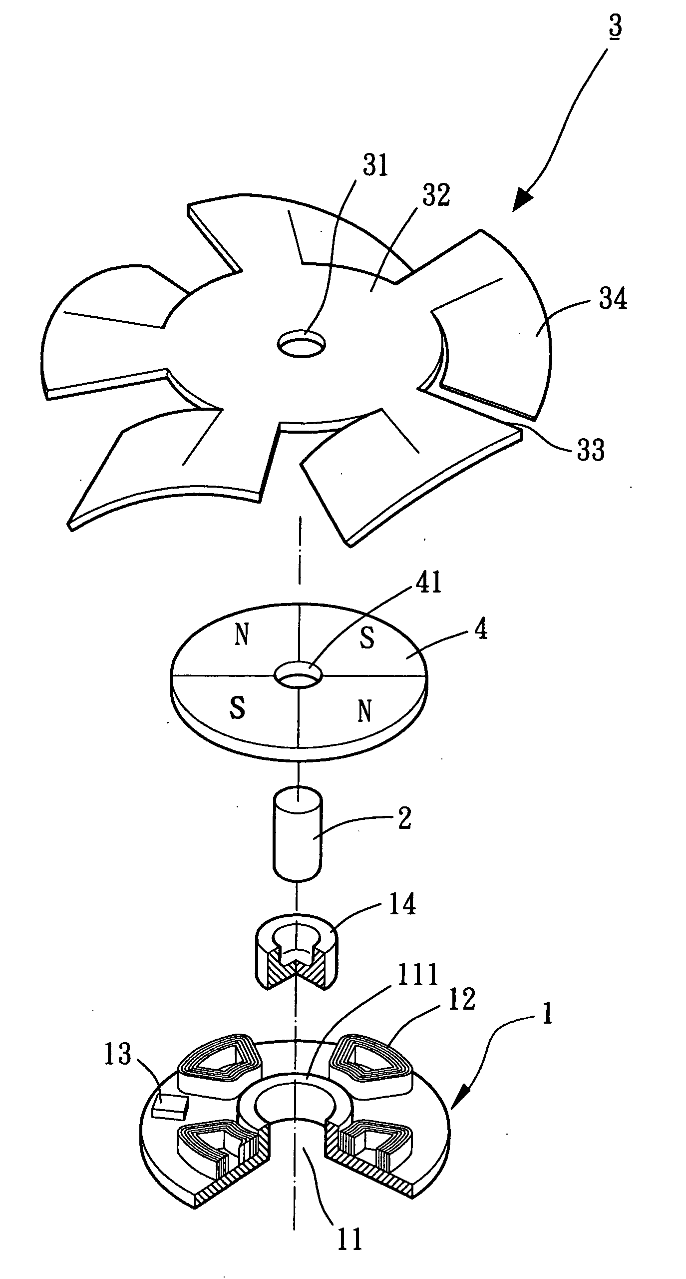
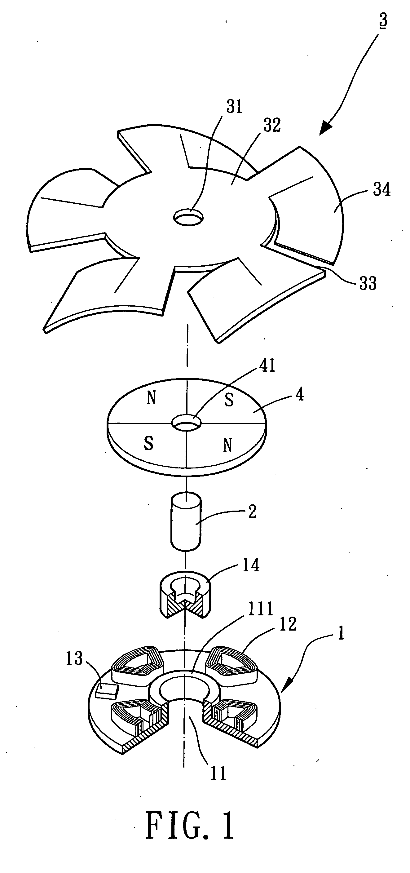
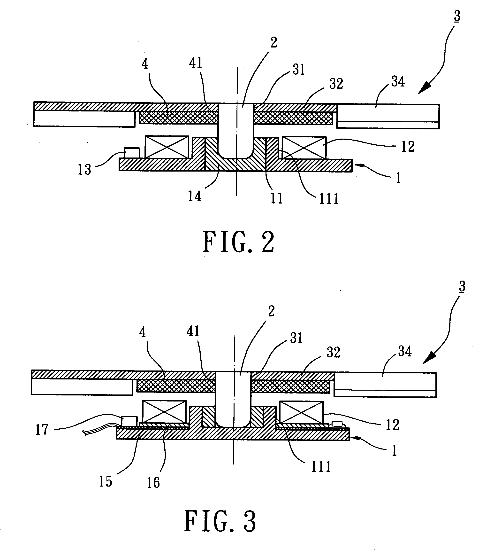
[0026] Referring now to FIGS. 1 and 2, a simplified fan device having a thin-type structure with a minimum air gap in accordance with a first embodiment of the present invention is disclosed and may be installed in a compact personal computer or a notebook (not shown). In the first embodiment, the fan device generally includes a base plate designated numeral 1, a shaft member designated numeral 2, a flat-type impeller designated numeral 3, and a magnet sheet designated numeral 4. In the illustrated embodiment, it will be understood that the base plate 1 of the fan device is the construction of a motor stator while the assembly of the shaft member 2, the flat-type impeller 3 and the magnet sheet 4 is the construction of a motor rotor. The combination the flat-type impeller 3 with the magnet sheet 4 of the fan device having the thin-type structure in accordance with the present invention has a thickness of about 3 mm or less than 3 mm. In other words, the thin-type structure of the fa...


PUM


Abstract

A simplified fan device includes a base plate, a flat-type impeller, a magnet sheet and a shaft member. The base plate includes an axial hole and at least one stator coil arranged thereon. The flat-type impeller is formed with an annular supporting plate, an assembling hole and a series of bent vanes. The magnet sheet provides with a center through hole and at least one pair of alternatively opposite magnetic poles (i.e. north pole and south pole). A first distal end of the shaft member is mounted to one of the assembling hole of the flat-type impeller and the center through hole of the magnet sheet or both. Correspondingly, a second distal end of the shaft member is extended through and rotatably received in a bearing member mounted in the axial hole of the base plate so as to constitute a thin-type structure.

Description

BACKGROUND OF THE INVENTION [0001] 1. Field of the Invention [0002] The present invention relates to a simplified fan device having a thin-type structure with a minimum air gap for reducing an axial thickness. Particularly, the present invention relates to the simplified fan device including a flat-type impeller to provide with an annular supporting plate and a set of bent vanes connected thereto. More particularly, the present invention relates to the flat-type impeller of the simplified fan device to permit the omission of an upraised wall of a hub portion for reducing the entire axial thickness of the fan device. [0003] 2. Description of the Related Art [0004] A conventional small-size fan device, as described in U.S. Pat. No. 5,217,351, entitled “SMALL FAN,” includes a fan housing and an impeller rotatably supported therein. The fan housing forms a base plate on which to provide with an axial tube and a pair of stator coils. In common practice, the axial tube accommodates a bear...

Claims


Application Information

Patent Timeline
Patent Type & Authority Applications(United States)
IPC IPC(8): H02K21/12H02K1/22F04B17/00
CPCF04D25/0653F04D29/325F04D29/38F04D29/054F04D29/056F04D29/002F05D2210/12F05D2260/60Y10S415/00Y10S417/00
Inventor HORNG, ALEXYIN, TSO-KUO
Owner SUNONWEALTH ELECTRIC MACHINE IND
Why Eureka
Try Eureka