Traction machine for elevator

A technology of traction machines and elevators, which is applied to elevators, electrical components, electromechanical devices, etc. in buildings, and can solve problems such as damaged bearings, short circuits in the internal coils of motors, and increased axial thickness of the whole machine, so as to reduce the axial thickness. Thickness, cost reduction effect

Inactive Publication Date: 2013-03-20
SHANGHAI MITSUBISHI ELEVATOR CO LTD
View PDF5 Cites 4 Cited by
  • Summary
  • Abstract
  • Description
  • Claims
  • Application Information

AI Technical Summary

Problems solved by technology

However, arranging the brushes and conductive rings at the shaft extension end will increase the axial thickness of the whole machine; and when the rotor rotates, the brush powder generated by the friction between the brushes and the conductive rings will easily invade the bearing and the inner coil of the motor , damage the bearing and easily cause a short circuit in the internal coil of the motor
Although relevant measures have been taken to block the intrusion of brush powder, there are still problems that cannot be solved fundamentally.

Method used


Image

  • Traction machine for elevator
  • Traction machine for elevator
  • Traction machine for elevator

Examples


Embodiment Construction

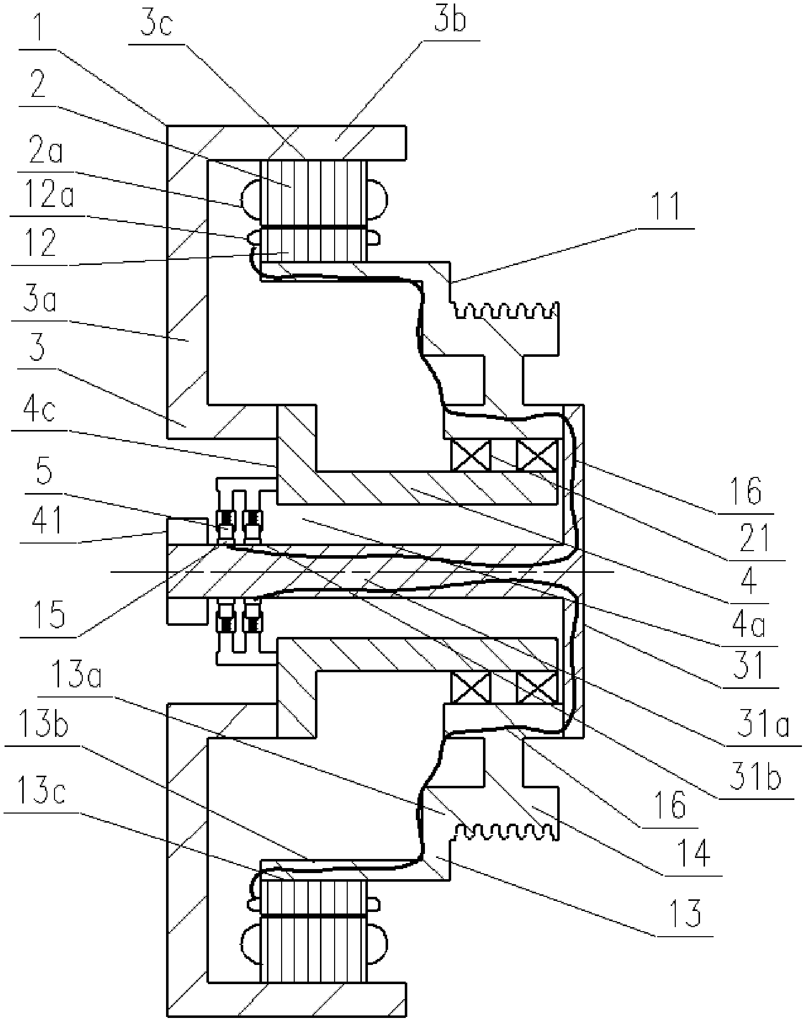
[0044] Such as image 3 Shown is the first embodiment of the elevator traction machine of the present invention, including a motor, a slip ring assembly, a fixed frame 1, and a rotating frame 11;

[0045] The motor comprises a stator 2 provided with a stator coil 2a, a rotor 12 provided with a rotor coil 12a, and the stator 2 is arranged opposite to the rotor 12;

[0046] The slip ring assembly includes a plurality of conductive rings 15 and a plurality of brushes 5, and each brush 5 is in contact with the corresponding conductive ring 15; the slip ring assembly is used to transfer electric energy to the rotor coil 12a;

[0047] The fixed frame 1 includes a fixed machine base 3 and a main shaft 4, the main shaft 4 and the fixed machine base 3 are split structures, and the main shaft 4 is fixedly connected to the fixed machine base 3;

[0048] The fixed base 3 has a hollow disc-shaped extension 3a extending radially outward, a cylindrical portion 3b bent from the extension 3a ...


PUM


Abstract

The invention discloses a traction machine for an elevator. The traction machine for the elevator comprises a motor, a collecting ring assembly, a fixed frame and a rotary frame. The collecting ring assembly comprises a plurality of conducting rings and a plurality of electric brushes. Each electric bush mutually contacts each corresponding conducting ring. The fixed frame comprises a fixed machine seat and a main shaft. The main shaft and the fixed machine seat are connected fixedly with each other. An electric brush installing part is arranged on the fixed frame. The plurality of electric brushes are arranged fixedly on the electric brush installing part. A rotor coil of the motor is connected electrically with the electric conducting ring through an electric conductor. The function of delivering electric power to the rotor coil is achieved by the conducting ring, the electric brushes and the electric conductor. According to the traction machine for the elevator, permanent magnetic steel with high cost is saved and cost of the traction machine is reduced obviously. The electric brushes and the conducting rings are arranged near the hollow portion of the main shaft so that inner space of the traction machine is fully used, the axial thickness of the complete machine is reduced so that the complete machine is thinned and applicable to an elevator with a small motor room or no motor room and the like and with requirement of thin traction machine.

Description

technical field [0001] The invention relates to an elevator driving device, in particular to an elevator traction machine. Background technique [0002] At present, the commonly used gearless traction machines for elevators generally realize the rotor excitation through permanent magnets. Such as figure 1 Shown is a gearless permanent magnet synchronous traction machine for elevators disclosed in Chinese invention patent ZL02111952.X. A permanent magnet is installed on the yoke of the rotor of the traction machine to realize rotor excitation. [0003] Since the permanent magnets satisfying the magnetic properties contain rare earth materials and are expensive, the cost of the traction machine is also high. Moreover, with the increase in the use of permanent magnets and the reduction in the stock of rare earth material resources, the price of permanent magnets will become higher and higher. [0004] In order to reduce costs, a synchronous traction machine (or synchronous m...

Claims


Application Information

Patent Timeline
Patent Type & Authority Applications(China)
IPC IPC(8): B66B11/04H02K13/00H02K5/04
Inventor 方凯李伟李洁李磊顾伟光
Owner SHANGHAI MITSUBISHI ELEVATOR CO LTD
Why Eureka
Try Eureka