Reduction gear

a technology of reduction gear and gear shaft, which is applied in the direction of gearing, wobble plate gearing, oblique crank gearing, etc., can solve the problems of increasing the thickness of gear reduction, unable to be downsized, and the difficulty of employing the above reduction gear for electronics devices such as digital cameras that are required to be downsized, so as to achieve the effect of easy change of the ratio between the input shaft and the output sha

Inactive Publication Date: 2010-03-30
SEIKO PRECISION CO LTD
View PDF18 Cites 4 Cited by
  • Summary
  • Abstract
  • Description
  • Claims
  • Application Information

AI Technical Summary

Benefits of technology

[0009]With such a configuration, the outputting member, the transmitting member, and the output shaft are aligned in the direction perpendicular to the input shaft. This allows the reduction gear to reduce the thickness thereof in the direction of the axis and to be downsized, as compared to when the input shaft, the extracting member, the transmitting member, and the output shaft be aligned in the direction of the axis. Therefore, the reduction gear can be downsized. Additionally, a rotational component of the external gear can be transmitted in the direction perpendicular to the input shaft.
[0012]Moreover, by changing in the number of teeth of at least one of the gears, a reduction ratio between the input shaft and the output shaft can be changed with easy without changing in the number of teeth of the external gear or those of the internal gear.
[0014]Additionally, as compared to where the output shaft is rotated by the belt member, the distance between the input shaft and the output shaft can be shortened. Therefore, the width, perpendicular to axial direction, of the reduction gear can be minimized.
[0016]With such a configuration, the output shaft can be positioned by the internal gear. This eliminates the need for separately providing a positioning member or a bearing portion for the output shaft, thus reducing the number of parts and facilitating the assembling process.
[0018]These arrangements enable a single member to position the reduction gear mechanism and the motor. This makes it possible to reduce the axial thickness of the reduction gear including the motor. Also, the single member enables the reduction gear mechanism and the motor to be positioned, so that it is possible to improve the assembling ability, leading to the reduced manufacturing cost.

Problems solved by technology

This causes a problem that the gear reduction increases in thickness thereof and cannot be downsized.
Consequently, it is difficult that an electronics device, such as a digital camera, required to be downsized employs the above reduction gear.

Method used


Image

  • Reduction gear
  • Reduction gear
  • Reduction gear

Examples


Embodiment Construction

[0024]A description will now be given, with reference to the accompanying drawings, an embodiment of the present invention.

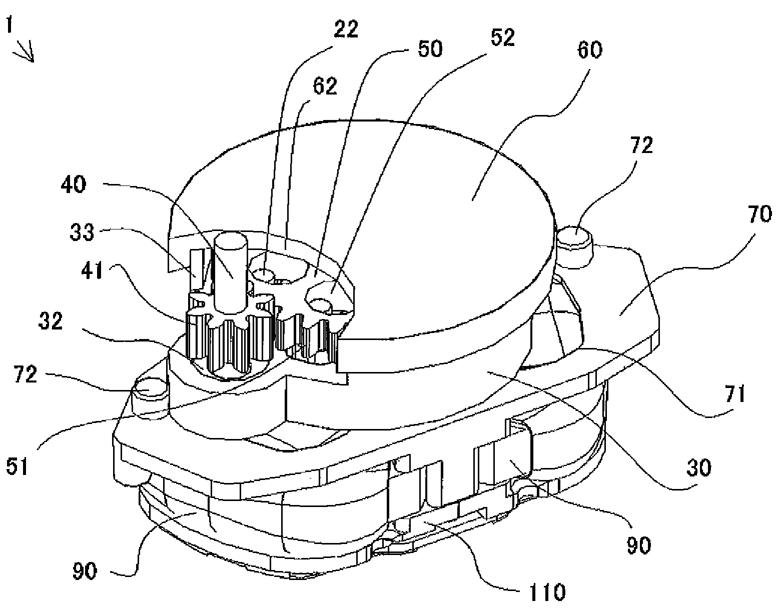
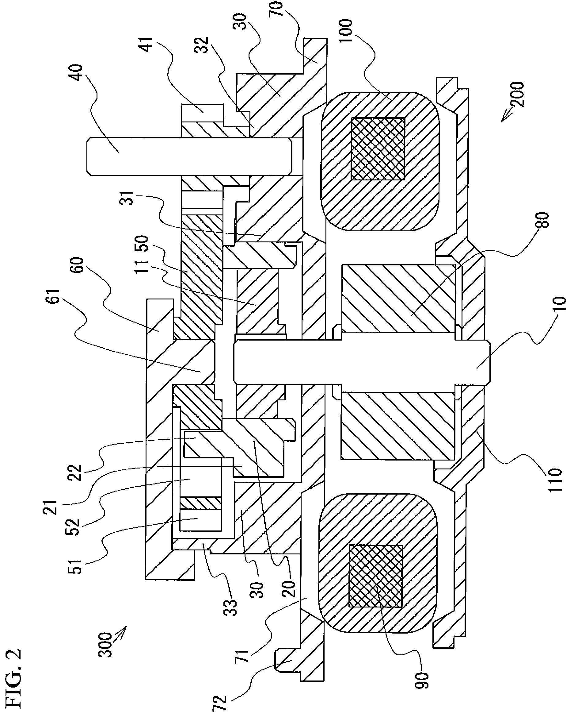
[0025]Referring to FIGS. 1 and 2, a reduction gear according to an embodiment of the present invention will be explained. FIG. 1 is a perspective view of the reduction gear. FIG. 2 is a cross sectional view of the reduction gear.

[0026]As shown in FIGS. 1 and 2, the reduction gear 1 includes: an input shaft 10; an eccentric body 11; an external gear 20 eccentrically rotatable about the input shaft 10; an internal gear 30 internally meshing with the external gear 20 and having a small number of teeth different from the external gear 20; an output shaft 40 for extracting a rotation of the external gear 20; a disk (extracting member) 50 for extracting only the rotation of the external gear 20; an upper cover 60; a positioning plate 70; a rotor 80; a stator 90; coil 100, and a motor cover 110. Additionally, a motor 200 includes the input shaft 10, the rotor 80, the s...


PUM


Abstract

A reduction gear includes a reduction mechanism, which includes: an external gear eccentrically rotatable about an input shaft; an internal gear internally meshing with the external gear and having a small number of difference between the teeth of the internal gear and the external gear; a disk for extracting only a rotational component of the external gear; an output shaft; and gears for transmitting the rotational component of the external gear from the disk to the output shaft. The disk, the gears and the output shaft are aligned in a direction perpendicular to an axial direction of the input shaft.

Description

[0001]This application is a continuation of international application PCT / JP2007 / 052238 filed Feb. 8, 2007.BACKGROUND OF THE INVENTION[0002]1. Field of the Invention[0003]The present invention relates to reduction gears, and more particularly, to a reduction gear including a reduction gear mechanism having an external gear eccentrically rotatable about an input shaft; an internal gear internally being meshed with the external gear and having a small number of difference between the teeth of the internal gear and the external gear, and an output shaft for extracting a rotation of the external gear.[0004]2. Description of the Related Art[0005]Conventionally, there has been known a reduction gear including an input shaft, an eccentric body rotated by the rotation of the input shaft, an external gear attached to the eccentric body and swung, an internal gear internally meshing with the external gear, and an output shaft coupled to the external gear through an extracting member for extra...

Claims


Application Information

Patent Timeline
Patent Type & Authority Patents(United States)
IPC IPC(8): F16H48/06F16H1/32F16H57/021F16H57/023
CPCF16H1/32F16H37/041F16H1/08F16H23/02
Inventor KAWAMOTO, HISASHI
Owner SEIKO PRECISION CO LTD
Why Eureka
Try Eureka