Miniature Heat-Dissipating Fan

a heat-dissipating fan and miniature technology, applied in the direction of dynamo-electric machines, piston pumps, non-positive displacement fluid engines, etc., can solve the problems of inability to minimize the dimensions the difficulty of reducing the entire axial thickness of the conventional heat-dissipating fan, and the inability to reduce the overall thickness of the miniature heat-dissipating fan

Active Publication Date: 2010-04-22
SUNONWEALTH ELECTRIC MACHINE IND
View PDF4 Cites 5 Cited by
  • Summary
  • Abstract
  • Description
  • Claims
  • Application Information

AI Technical Summary

Benefits of technology

[0010]It is therefore the primary objective of this invention to provide a miniature heat-dissipating fan that overcomes the problems of the prior art described above to avoid electromagnetic interference effectively and reduce an overall thickness of the miniature heat-dissipating fan.

Problems solved by technology

First, the metal ring 862 provides a leakage flux absorbing effect during rotation of the impeller rotor 86 that is driven by alternating magnetic fields generated by the coils 84. However, the metal ring 862 only can prevent an occurrence of magnetic flux leakage above the coils 84 and the magnet 861. And thus, magnetic flux that is generated by the coils 84 and doesn't react with the magnet 861 results in magnetic flux leakage under the coils 84 to cause electromagnetic interference (EMI), so that functions of the electronic device or electronic apparatus may easily be affected.
Second, the current trend of research and development in electronic products is miniaturization. However, the circuit board 83 and the coils 84 both have fixed axial thicknesses, which lead to a difficulty in reducing the entire axial thickness of the conventional heat-dissipating fan 8. As a result, minimizing dimensions of the conventional heat-dissipating fan 8 is not feasible, so that it is hard to apply the conventional heat-dissipating fan 8 to a miniature electronic device or electronic apparatus.
However, owing to fixed axial thicknesses of the base plate 91 and the stator coils 912 of the conventional heat-dissipating fan 9, it's difficult to reduce the entire axial thickness of the conventional heat-dissipating fan 9, too.
And also a difficulty of minimizing dimensions of the conventional heat-dissipating fan 9 is caused, and thereby the conventional heat-dissipating fan 9 is hard to be mounted to a miniature electronic device or electronic apparatus.

Method used


Image

  • Miniature Heat-Dissipating Fan
  • Miniature Heat-Dissipating Fan
  • Miniature Heat-Dissipating Fan

Examples


Embodiment Construction

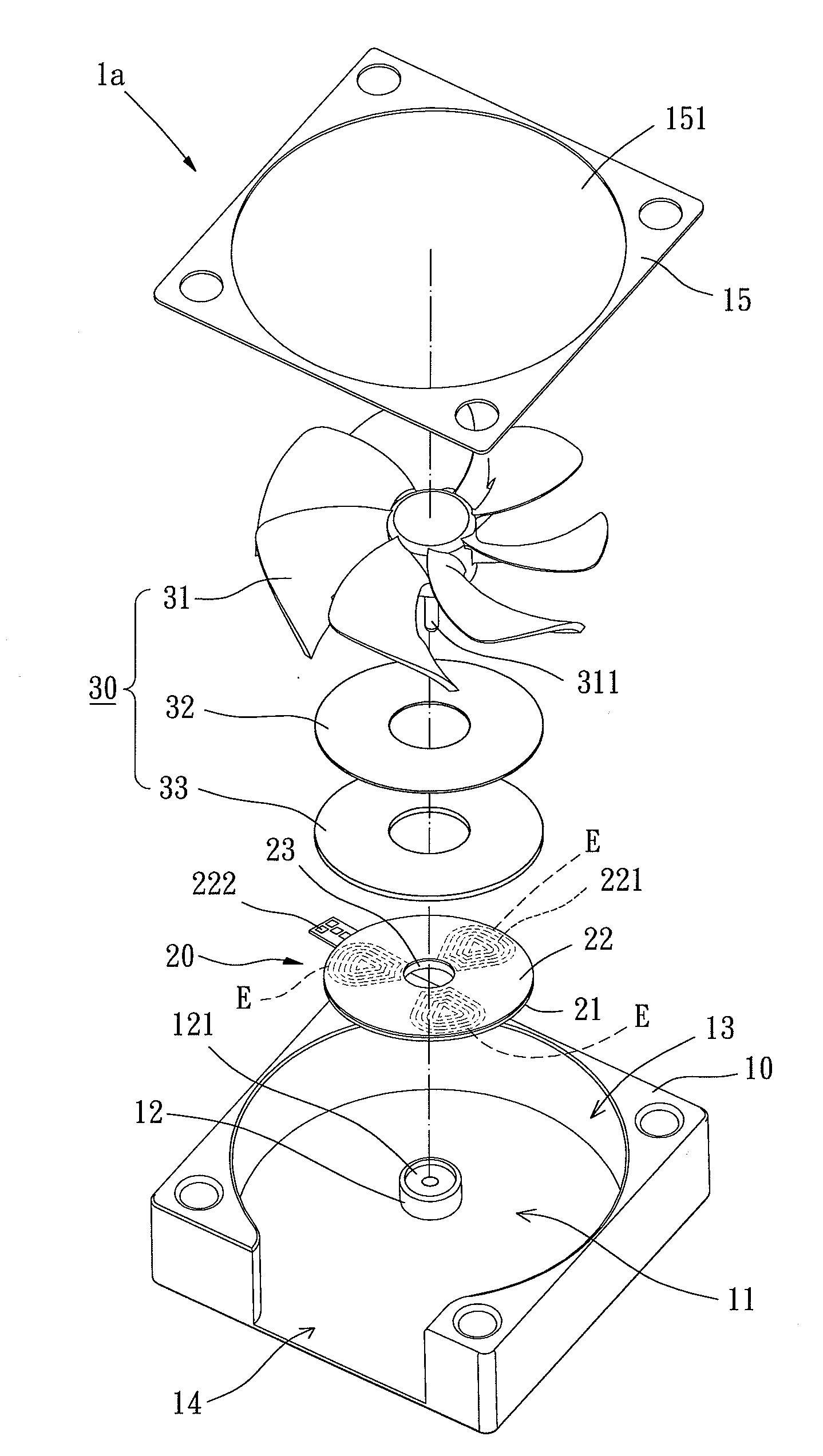
[0031]A miniature heat-dissipating fan of a first embodiment according to the preferred teachings of the present invention is shown in FIGS. 5 and 6 of the drawings. According to the first embodiment form shown, the miniature heat-dissipating fan designated numeral “1a” includes a casing 10, a stator 20 and a rotor 30.

[0032]The casing 10 defines a compartment 11 and has a shaft tube 12 in the compartment 11. The shaft tube 12 preferably receives a bearing 121. The casing 10 has an air inlet 13 and an air outlet 14 both connecting to the compartment 11. Furthermore, a lid 15 is mounted to one side of the casing 10 where the air inlet 13 is formed, with the lid 15 having a through hole 151 aligned with the air inlet 13.

[0033]The stator 20 has a first leakage flux absorber 21 made of magnetically conductive materials. Preferably, a printed circuit board is attached to a surface of the first leakage flux absorber 21 and a coil layer 22 is formed on the printed circuit board by layout. T...


PUM


Abstract

A miniature heat-dissipating fan includes a stator and a rotor. The stator has a first leakage flux absorber, a coil layer arranged on the first leakage flux absorber, and a hole. The coil layer has a plurality of coils and the hole passes through the first leakage flux absorber and the coil layer. The rotor has an impeller, a second leakage flux absorber and a permanent magnet. The second leakage flux absorber and the permanent magnet are attached to a bottom of the impeller, such that the rotor is rotatably coupled to the stator. Consequently, magnetic flux leakage under the stator is prevented to assure that electromagnetic interference will never be caused, and an overall axial thickness of the miniature heat-dissipating fan is reduced by the configuration of the stator.

Description

BACKGROUND OF THE INVENTION[0001]1. Field of the Invention[0002]The present invention relates to a heat-dissipating fan and, more particularly, to a miniature heat-dissipating fan that includes a stator having a reduced axial thickness.[0003]2. Description of the Related Art[0004]A conventional heat-dissipating fan is described in China Patent Publication No. 101060766 (with Application No. 200610072272.8) entitled “SMALL HEAT-DISSIPATING DEVICE”. Referring to FIGS. 1 and 2, the conventional heat-dissipating fan 8 includes a casing 81 defining a compartment 811 and a lid 82 mounted on a top of the casing 81. A circuit board 83 and coils 84 are mounted to a base 812 delimiting a bottom of the compartment 811. An axial tube 813 extends from a center portion of the base 812, with an impeller rotor 86 being coupled rotatably in the compartment 811 by the axial tube 813. Furthermore, at least two positioning members 85 are provided on the base 812 and located outside the axial tube 813. ...

Claims


Application Information

Patent Timeline
Patent Type & Authority Applications(United States)
IPC IPC(8): F04D25/08
CPCF04D25/0653
Inventor HORNG, ALEXYIN, TSO-KUO
Owner SUNONWEALTH ELECTRIC MACHINE IND
Why Eureka
Try Eureka