Analyte assay structure in microfluidic chip for quantitative analysis and method for using the same

Inactive Publication Date: 2007-05-31
IND TECH RES INST
View PDF14 Cites 138 Cited by
  • Summary
  • Abstract
  • Description
  • Claims
  • Application Information

AI Technical Summary

Benefits of technology

[0018] The object of the present invention is to provide a sample assay structure in a microfluidic chip for quantitative analysis which comprises a sample inlet port for inputting a testing sample; an analyte detection region, coupled to the sample inlet port, consisting of at least one microfluidic channel, in which a plurality of immobilized subs

Problems solved by technology

Liquid assays are usually limited to hospitals or medical centers because of the bulky size and expense of the instruments, as well as the need for a licensed professional to process the assay.
Dry strip assays are often qualitative tests because of the difficulty in obtaining accurate readings.
However, a shorter strip implies a shorter reaction zone and poor resolution, making it difficult for a user to read the length of the colored zone.
As shown in FIG. 1, the front edge of the color changed region may have an irregular shape, making it difficult to read the colored length.
Speed of the test sample: The quality of the fiber based strip dramatically affects the opportunities for contact and reaction between the analyte and the immobilized substances.
A strip with poor fi

Method used


Image

  • Analyte assay structure in microfluidic chip for quantitative analysis and method for using the same
  • Analyte assay structure in microfluidic chip for quantitative analysis and method for using the same
  • Analyte assay structure in microfluidic chip for quantitative analysis and method for using the same

Examples


example 1

Applying Speed Control to a Quantitative Assay of the Analyte

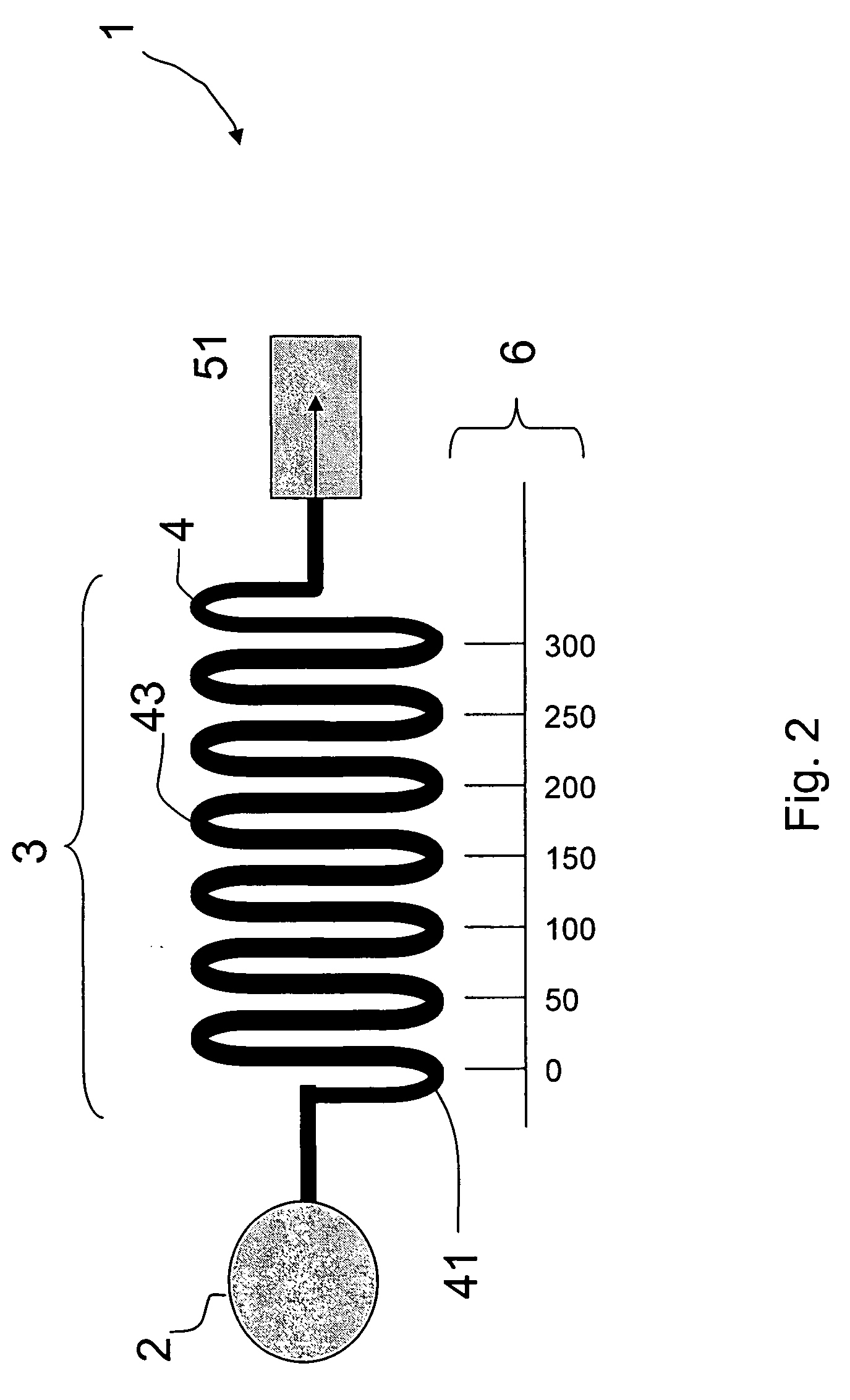
[0094] In this example photolithoghaphy of MEMS process and polymer materials were applied to make the sample assay structure. Two samples with different quantities of the analyte were tested using the quantitative analyte assay structure presented in the present invention. The structure was constructed of an upper and a lower substrate. The upper substrate was made of hydrophobic polymer on which a serpentine thin channel functions as the sample path and two wells at its two ends function as the sample inlet port and the waste well. The lower substrate was made of glass on which chemical function groups were grafted. The assembly of the two substrates formed the sample assay structure. An external pump was hooked up to the waste well to drive the sample in the microfluidic channel 100μm in both width and depth. The layout of the chip is similar to the one shown in FIG. 2, each straight section of the U-shaped channel (L)...

example 2

Applying Speed Control and Local Dimension Modifications to a Quantitative Assay of the Analyte

[0096] In this example the materials used and the manufacturing process applied to the assay structure were the same as those in Example 1. However, this example differs from the preceding one in that there were local modifications to the dimensions of the channel—a type of passive fluid modulating members was introduced in the present case. In the analyte detection region the 300 um wide channel was reduced in width unsymmetrically to 150 um at every 2 mm distance.

[0097] A sample assay structure in the microfluidic chip in this case modulated the reaction by controlling flow speed and by variations in the geometric shapes of the microfluidic channel for quantitative analyte analysis. Goat-anti-mouse-IgG, 5.6 mg / ml was immobilized on the wall of the channel. An active external pump is used to drive the sample making it flow at 12 mm / min, faster than that in Example 1. Two different sampl...

example 3

Applying Speed Control and Modifications to Local Dimension and Shape to a Quantitative Assay of the Analyte

[0098] In this example the materials used, the manufacturing process applied, and the alternating width of the channel (300 um full width narrowed unsymmetrically to 150 um) in the assay structure were the same as those in Example 2. The flow was driven at 12 mm / min as in Example 2.

[0099] However, in this example protrusions were located in the analyte detection region so local turbulent flow enhanced the opportunity for contact between the analyte and the immobilized substances. Goat-anti-mouse-IgC, 5.6 mg / ml was immobilized on the wall of the channel.

[0100] An active external pump was used to drive the sample making it flow at 12 mm / min, faster than in Example 1. Two different samples were tested on two chips of the same kind. Chip 1 had 6 ul of labeled analyte Mouse-IgG CGC, OD540=50, while Chip 2 had 3 ul of labeled analyte Mouse-IgG CGC, OD540=50 diluted in 3 ul of wat...


PUM

PropertyMeasurementUnit
Lengthaaaaaaaaaa
Concentrationaaaaaaaaaa
Volumeaaaaaaaaaa

Abstract

The object of the present invention is to provide a sample assay structure in a microfluidic chip for quantitative analysis which comprises a sample inlet port for inputting a testing sample; an analyte detection region, coupled to the sample inlet port, consisting of at least one microfluidic channel, in which a plurality of immobilized substances capable of reacting with the analyte are placed; and a fluid driving device, capable of controlling the speed of the flow of the test sample through the analyte detection region, allowing the quantity of the analyte be indicated by the length of the portion of the microfluidic channel where the analyte reacted with the immobilized substances.

Description

BACKGROUND OF THE INVENTION [0001] 1. Field of the Invention [0002] The present invention relates to a sample assay structure in microfluidic chip for quantitative analysis without the use of an instrument. [0003] 2. Description of Related Art [0004] Many applications of clinical biochemical assay focus on the detection of the specific biochemical substances or pathogens that reflect the health or illness of a patient or the effects of medical treatment. The detection of biological and chemical substances, however, can also be applied to screening for drug abuse, to industrial manufacturing processes, to detect environmental pollution, and to the assay of plant and animal samples. [0005] The test sample for the assay is application-dependent. Drug screening or the assay of animal samples may use fluids from human or animals, such as blood, urine, saliva or serum. Industrial manufacturing process or environmental detection can use liquid samples from the manufacturing process and / or ...

Claims


Application Information

Patent Timeline
IPC IPC(8): C12Q1/68C12M3/00
CPCB01L3/502746B01L2300/0636B01L2300/0816B01L2300/0861B01L2400/0406B01L2400/0487B01L2400/086B01L2400/088G01N33/54373
Inventor WU, BI-CHUYOUNG, GIN-SHU
Owner IND TECH RES INST
Why Eureka
Try Eureka