
Decorative waterfall with planter

a planter and decorative technology, applied in the field of decorative waterfalls, can solve the problems of not having the appearance of a miniature natural waterfall, and none of the integrated planters for holding living plants,

Inactive Publication Date: 2007-06-14
BARNHILL PHILIP SCOTT
View PDF11 Cites 14 Cited by
  • Summary
  • Abstract
  • Description
  • Claims
  • Application Information

AI Technical Summary

Benefits of technology

[0023]FIG. 5 is a cut away view of the waterfall with integrated planter, sh

Problems solved by technology

But none has the appearance of a simulated miniature natural waterfall.
Additionally, none incorporates an integrated planter for holding living plants.

Method used


Image

  • Decorative waterfall with planter
  • Decorative waterfall with planter
  • Decorative waterfall with planter

Examples


Embodiment Construction

[0024] Detailed embodiments of the present invention are disclosed herein. It is to be understood, however, that the disclosed embodiments are merely exemplary of the invention and that the invention may be embodied in various and alternative forms. Therefore, specified structural and functional details disclosed herein are not to be interpreted as limitations, but merely as a basis for the claims and as a representative basis for teaching one skilled in the art to variously employ the present invention.

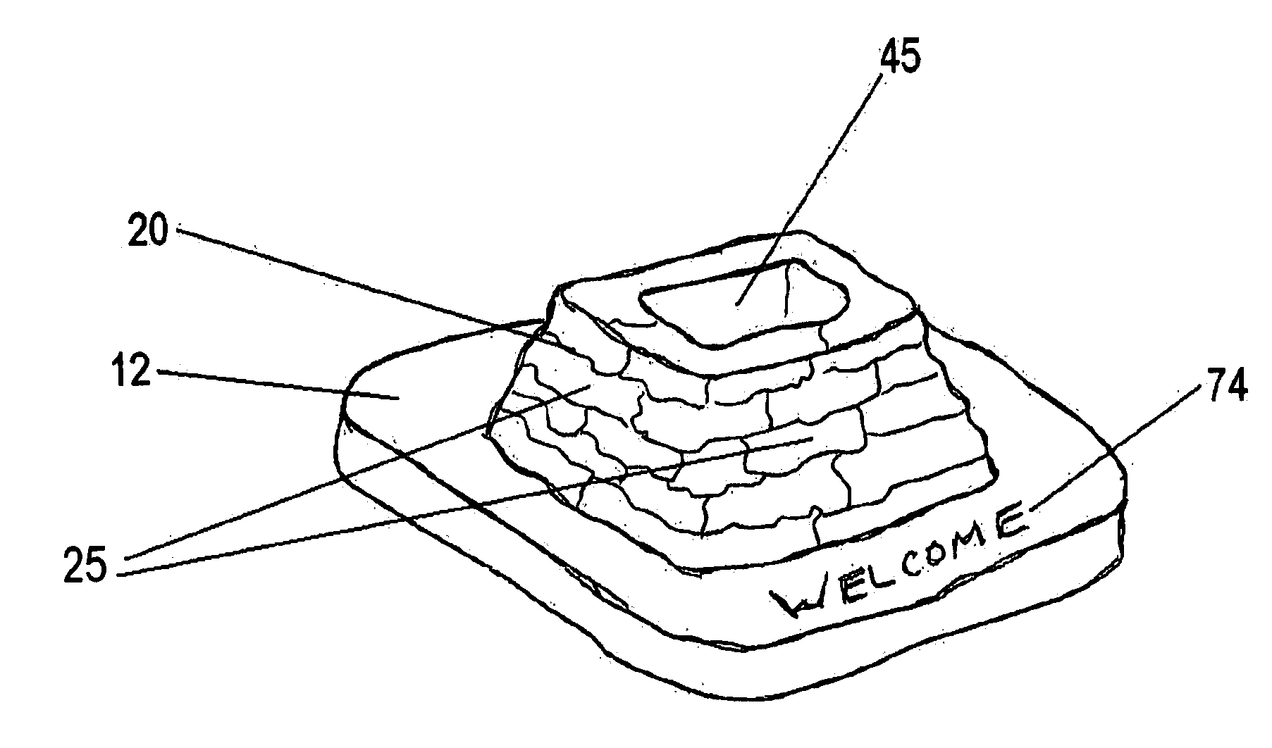
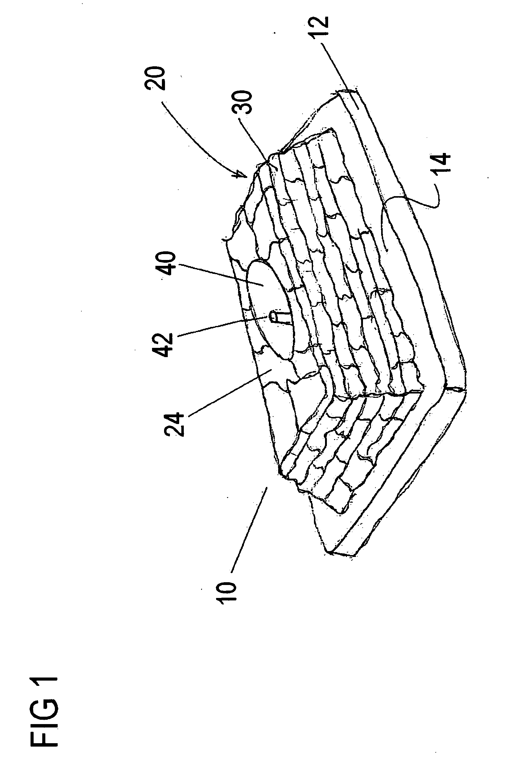
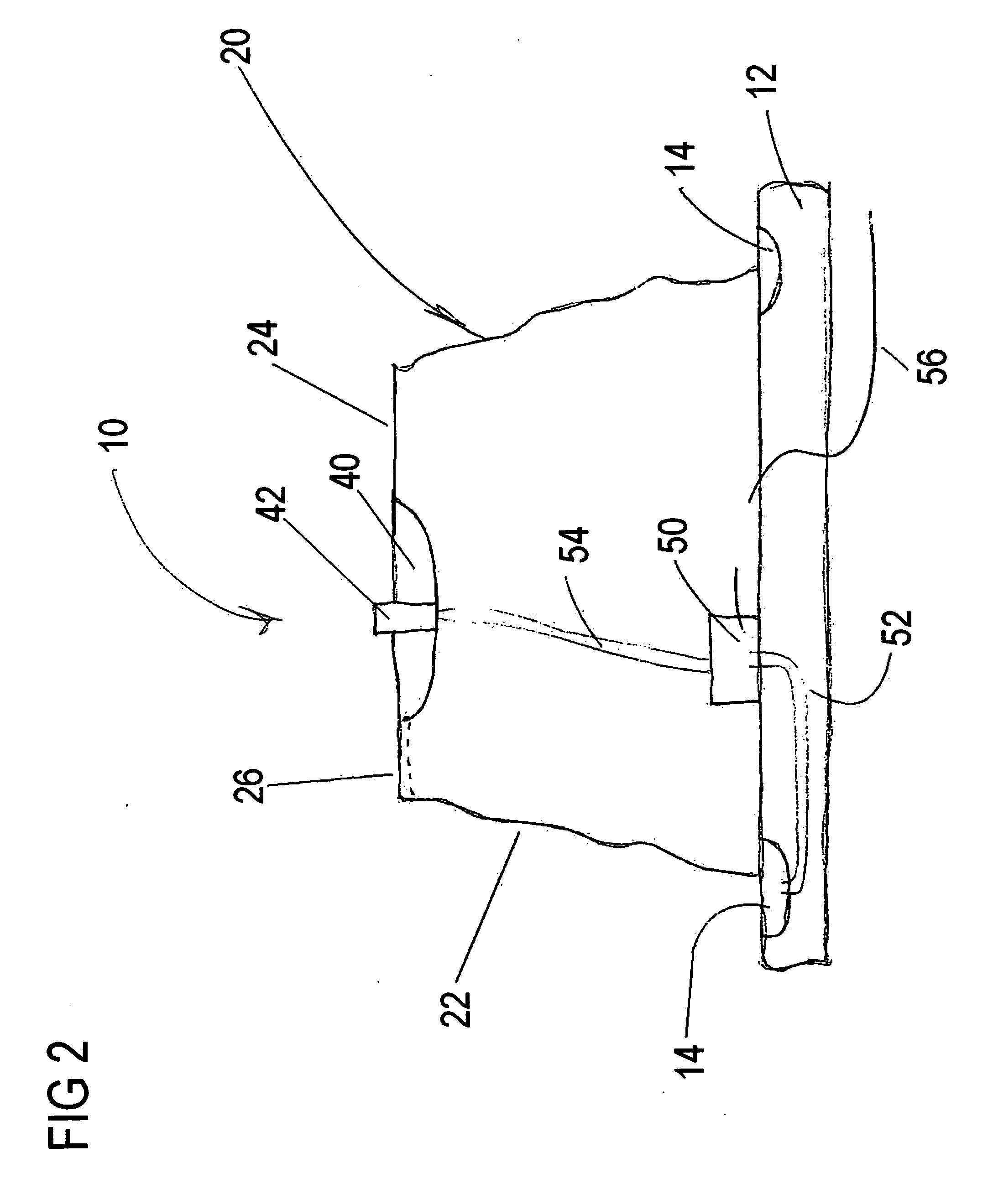
[0025] Referring now in more detail to the drawings, FIGS. 1, 2&3. FIG. 1 shows the waterfall 10 which is comprised of a base 12 and a pedestal 20. In the preferred embodiment, the pedestal 20 is constructed from a multiplicity of blocks 30. In the preferred embodiment the multiplicity of blocks 30 are made of natural stone. In the most preferred embodiment, the multiplicity of blocks 30 are small flat pieces of limestone. In alternate embodiments, the multiplicity of blocks 30 can ...


PUM


Abstract

A decorative waterfall containing an integrated planter is disclosed. The decorative waterfall contains a planter integrated within the main body of the waterfall and is constructed of natural or man made stone to create the appearance of a miniature natural waterfall.

Description

CROSS REFERENCE TO RELATED APPLICATIONS [0001] This application is a continuation-in-part of U.S. patent application Ser. No. 11 / 521,894 filed Sep. 15, 2006, and also claims priority to U.S. provisional application Ser. No. 60 / 749,898, filed on Dec. 14, 2005 and incorporated herein by reference.STATEMENT REGARDING FEDERALLY SPONSORED RESEARCH OR DEVELOPMENT [0002] Not Applicable THE NAMES OF THE PARTIES TO A JOINT RESEARCH AGREEMENT [0003] Not Applicable INCORPORATION-BY-REFERENCE OF MATERIAL SUBMITTED ON A COMPACT DISC [0004] Not Applicable BACKGROUND OF THE INVENTION [0005] 1. Field of the Invention [0006] The present invention relates to a decorative waterfall incorporating an integrated planter. [0007] 2. Description of the Related Art [0008] There are many decorative fountains and waterfalls known in the art. Many are large and used as outdoor decoration and water features, and many others are smaller and used as indoor decorations. In general, the larger outdoor fountains are ...

Claims


Application Information

Patent Timeline
IPC IPC(8): B05B17/08A01G9/02
CPCA01G9/02A47G7/08B05B17/08
Inventor BARNHILL, PHILIP SCOTT
Owner BARNHILL PHILIP SCOTT
Learn More