Air bag with a supported channel

a technology of air bags and supports, which is applied in the direction of pedestrian/occupant safety arrangements, vehicular safety arrangements, vehicle components, etc., can solve the problem of moving of the fabric member, and achieve the effect of restricting ballooning

Inactive Publication Date: 2007-06-14
GM GLOBAL TECH OPERATIONS LLC
View PDF8 Cites 51 Cited by
  • Summary
  • Abstract
  • Description
  • Claims
  • Application Information

AI Technical Summary

Benefits of technology

[0003] The present invention provides an air bag system including an inflator operable to release inflation fluid, and an inflatable cushion having a lower region and inflatable upon release of inflation fluid from the inflator, with the cushion defining a channel within the lower region thereof. The channel preferably has a U-shaped or a V-shaped cross-section, and may be configured to extend from the front to the rear of the inflatable cushion. At least one tether may support the channel during inflation of the cushion. The tether preferably attaches to the inflatable cushion to restrict ballooning during inflation thereof. The channel may be formed within the lower region by sewing. The air bag system may include a sensing tether operable to modify release of inflation fluid if an obstacle interferes with the channel during inflation. The sensing tether itself may further support the channel during inflation. A fabric member may at least partially cover the channel to define an end channel wall. In one aspect of the invention, inflation of the cushion beyond a predetermined depth at least partially detaches the fabric member from the cushion. In another aspect of the invention, the fabric member is movable between a first position wherein the end channel wall has a first area, and a second position wherein the end channel wall has a second area, with the second area being greater than the first area. A retention member may retain the fabric member in the first position. The retention member may be frangible, such that inflation of the cushion beyond a predetermined depth breaks the retention member, thereby causing the fabric member to move to the second position.

Problems solved by technology

The retention member may be frangible, such that inflation of the cushion beyond a predetermined depth breaks the retention member, thereby causing the fabric member to move to the second position.

Method used


Image

  • Air bag with a supported channel
  • Air bag with a supported channel
  • Air bag with a supported channel

Examples


second embodiment

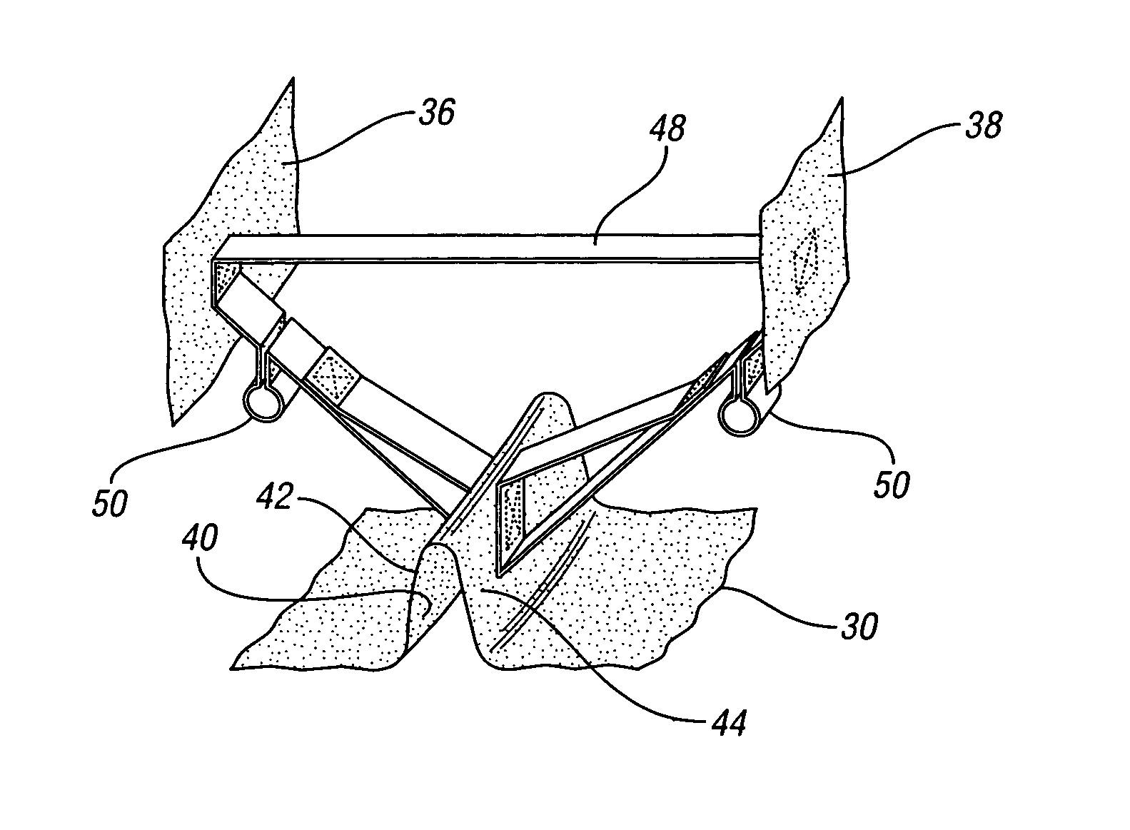
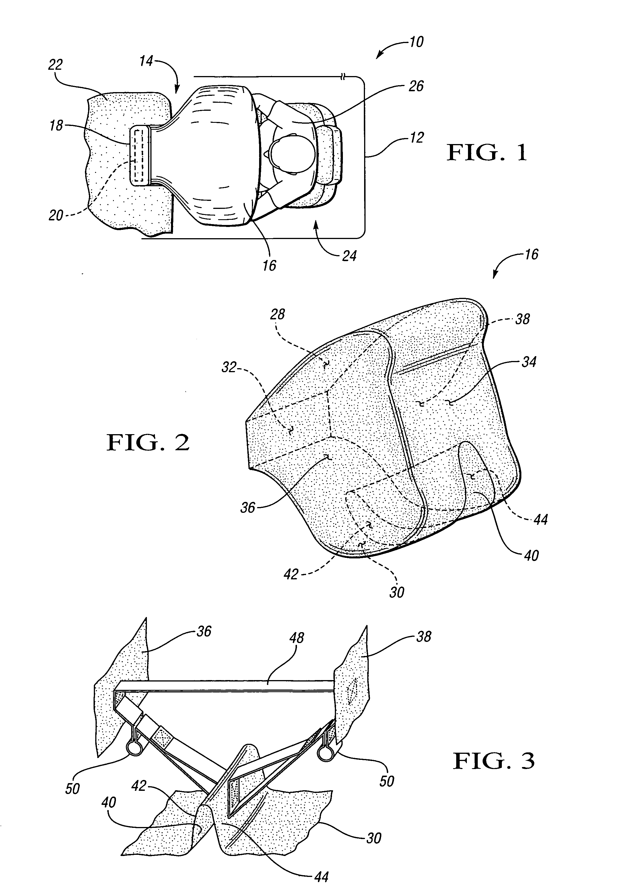
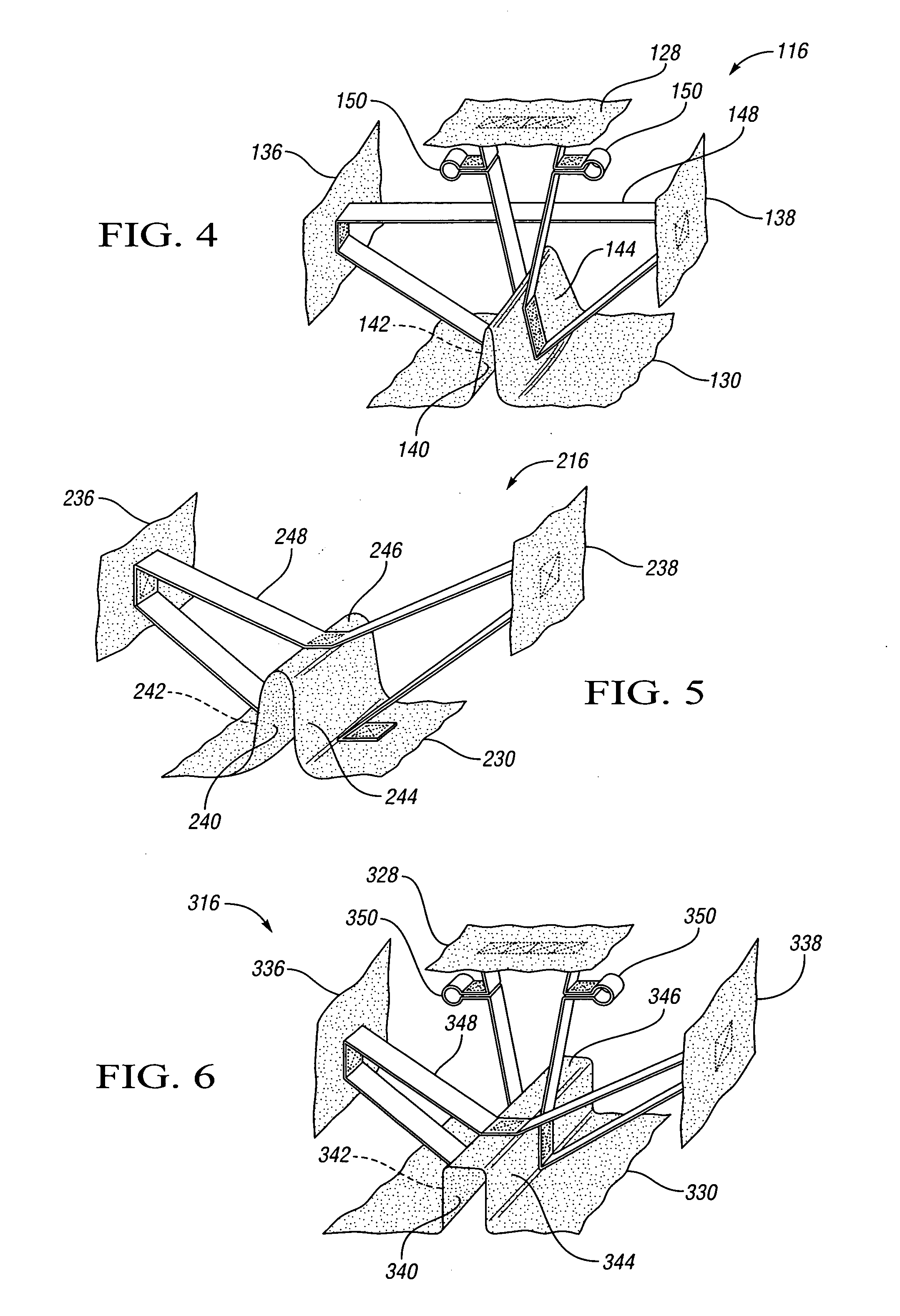
[0026]FIG. 4 shows an inflatable cushion 116 incorporating the present invention. A first tether 148 at least partially supports a substantially V-shaped channel 140 defined by an inflatable cushion 116. Specifically, the channel 140 is disposed within a lower region 130 of the inflatable cushion 116. The first tether 148 attaches to the channel 140 at first and second channel walls 142, 144, and to the inflatable cushion 116 at fifth and sixth regions 136, 138 and a second region 128. The first tether 148 includes loops 150, with tear stitching forming the loops 150 to allow the first tether 148 to support the channel 140 when the inflatable cushion 116 reaches varying depths.

third embodiment

[0027]FIG. 5 shows an inflatable cushion 216 incorporating the present invention. A first tether 248 at least partially supports a channel 240 defined by an inflatable cushion 216 and disposed within a lower region 230 of the inflatable cushion 216. Specifically, the inflatable cushion 216 defines first, second and third channel walls 242, 244, 246 within the lower region 230, such that the channel 240 is substantially U-shaped. In this embodiment, the first tether 248 attaches to the inflatable cushion 216 at five attachment points: the lower region 230 at a bottom of both the first and second channel walls 242, 244, a fifth region 236, a sixth region 238, and the third channel wall 246.

fourth embodiment

[0028]FIG. 6 shows an inflatable cushion 316 incorporating the present invention. A first tether 348 at least partially supports a channel 340 defined by an inflatable cushion 316 and within a lower region 330 of the inflatable cushion 316. The inflatable cushion 316 defines first, second and third channel walls 342, 344, 346 within the lower region 330, thereby imparting a U-shape to the channel 340. The first tether 348 attaches to the first, second and third channel walls 342, 344, 346, fifth and sixth regions 336, 338, and a second region 328. The first tether 348 includes loops 350, with tear stitching forming the loops 350 to allow the first tether 348 to support the channel 340 when the inflatable cushion 316 reaches varying depths as described with respect to previous embodiments.


PUM


Abstract

An air bag system includes an inflator operable to release inflation fluid, and an inflatable cushion having an lower region and inflatable upon release of inflation fluid from the inflator, with the cushion defining a channel within the lower region thereof. At least one tether may support the channel during inflation of the cushion. A fabric member may at least partially cover the channel to define an end channel wall. The fabric member may detach from the cushion if the cushion inflates beyond a predetermined depth, or the fabric member may be movable between a first position and a second position to increase the area of the end channel wall. A retention member may retain the fabric member in the first position. The retention member may be frangible, such that inflation of the cushion beyond the predetermined depth breaks the retention member.

Description

TECHNICAL FIELD [0001] This invention relates to an automotive vehicle air bag system, and more particularly to an air bag cushion having a supported channel integrally formed therein. BACKGROUND OF THE INVENTION [0002] Air bag systems in automotive vehicles generally include an air bag cushion that is designed to deploy within a passenger compartment of the automotive vehicle when triggered by a sensor signal. For example, air bag systems might be deployed upon sudden deceleration of a vehicle or upon impact of the vehicle with another object. The art continues to investigate improvements for air bag systems. SUMMARY OF THE INVENTION [0003] The present invention provides an air bag system including an inflator operable to release inflation fluid, and an inflatable cushion having a lower region and inflatable upon release of inflation fluid from the inflator, with the cushion defining a channel within the lower region thereof. The channel preferably has a U-shaped or a V-shaped cros...

Claims


Application Information

Patent Timeline
Patent Type & Authority Applications(United States)
IPC IPC(8): B60R21/23
CPCB60R21/231B60R21/2338B60R21/2342B60R21/239B60R2021/23382B60R2021/23384
Inventor THOMAS, SCOTT D.KUMKOSKI, JAMES M.
Owner GM GLOBAL TECH OPERATIONS LLC
Why Eureka
Try Eureka