Constant voltage source with output current limitation

a constant voltage source and output current technology, applied in the direction of electric variable regulation, process and machine control, instruments, etc., can solve the problems of reducing the oscillation tendency of the array, no longer applying second feedback, etc., and achieve the effect of higher input or supply voltages

Active Publication Date: 2007-06-14
ATMEL CORP
View PDF5 Cites 4 Cited by
  • Summary
  • Abstract
  • Description
  • Claims
  • Application Information

AI Technical Summary

Benefits of technology

[0014] In addition, the series connection of the transistors of the first pair and the transistors of the second pair advantageously make it possible to use higher input or supply voltages.
[0016] In the prior-art circuit, the output signal of a differential amplifier is used directly for controlling an output current-power transistor, as a result of which undesirable reactions by the power transistor to the control signal are possible. These undesirable reactions are avoided or at least reduced by the use of the current mirror, which has a high output resistance.
[0024] The second and the third transistors can be made as high-blocking transistors. As a result, higher input or supply voltages can be used advantageously.

Problems solved by technology

The second feedback no longer applies at all due to the control signal limitation which is independent of the actual value of the output current.
It turned out that the oscillation tendency of the array declines considerably as a result.

Method used


Image

  • Constant voltage source with output current limitation
  • Constant voltage source with output current limitation
  • Constant voltage source with output current limitation

Examples


Embodiment Construction

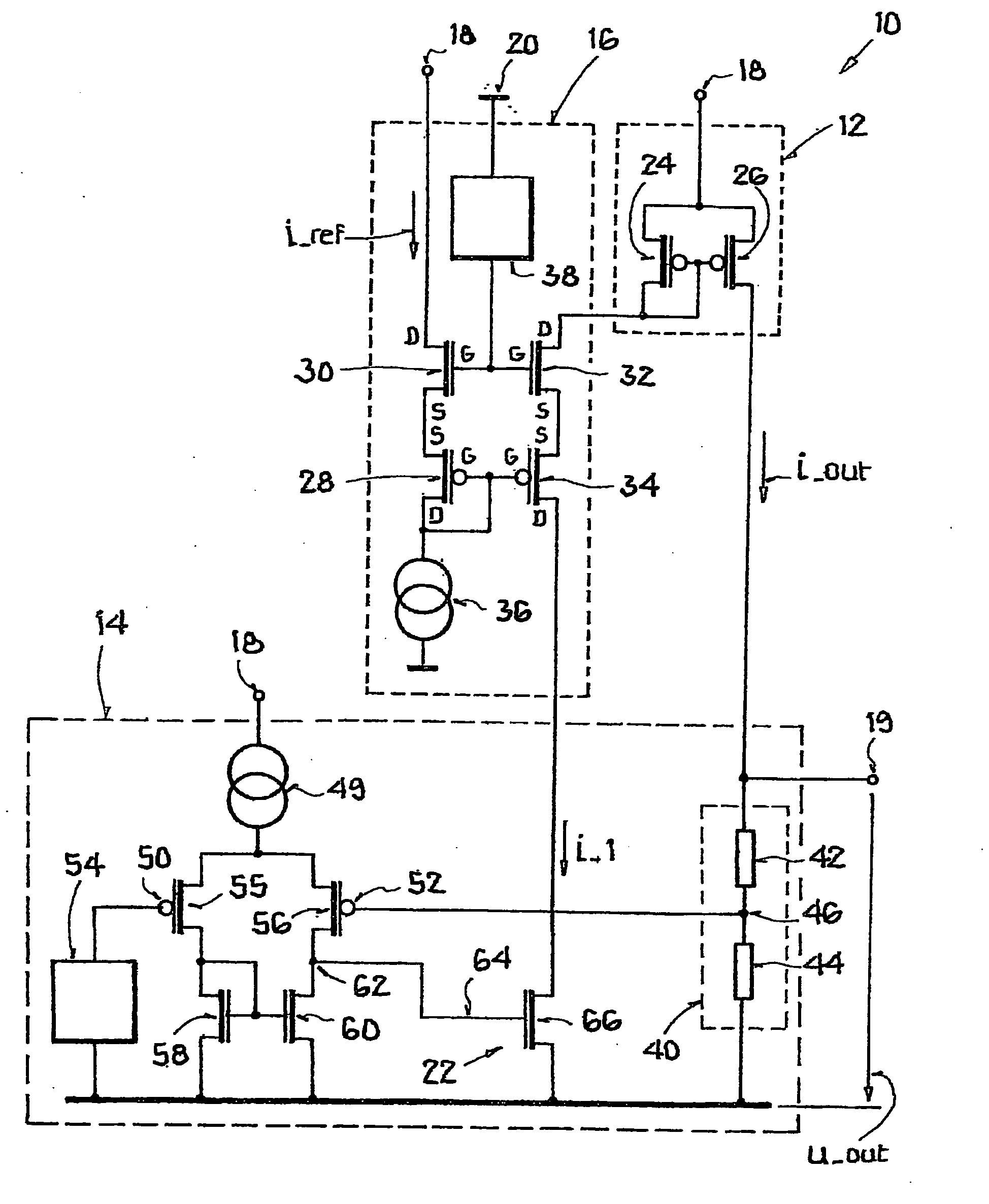
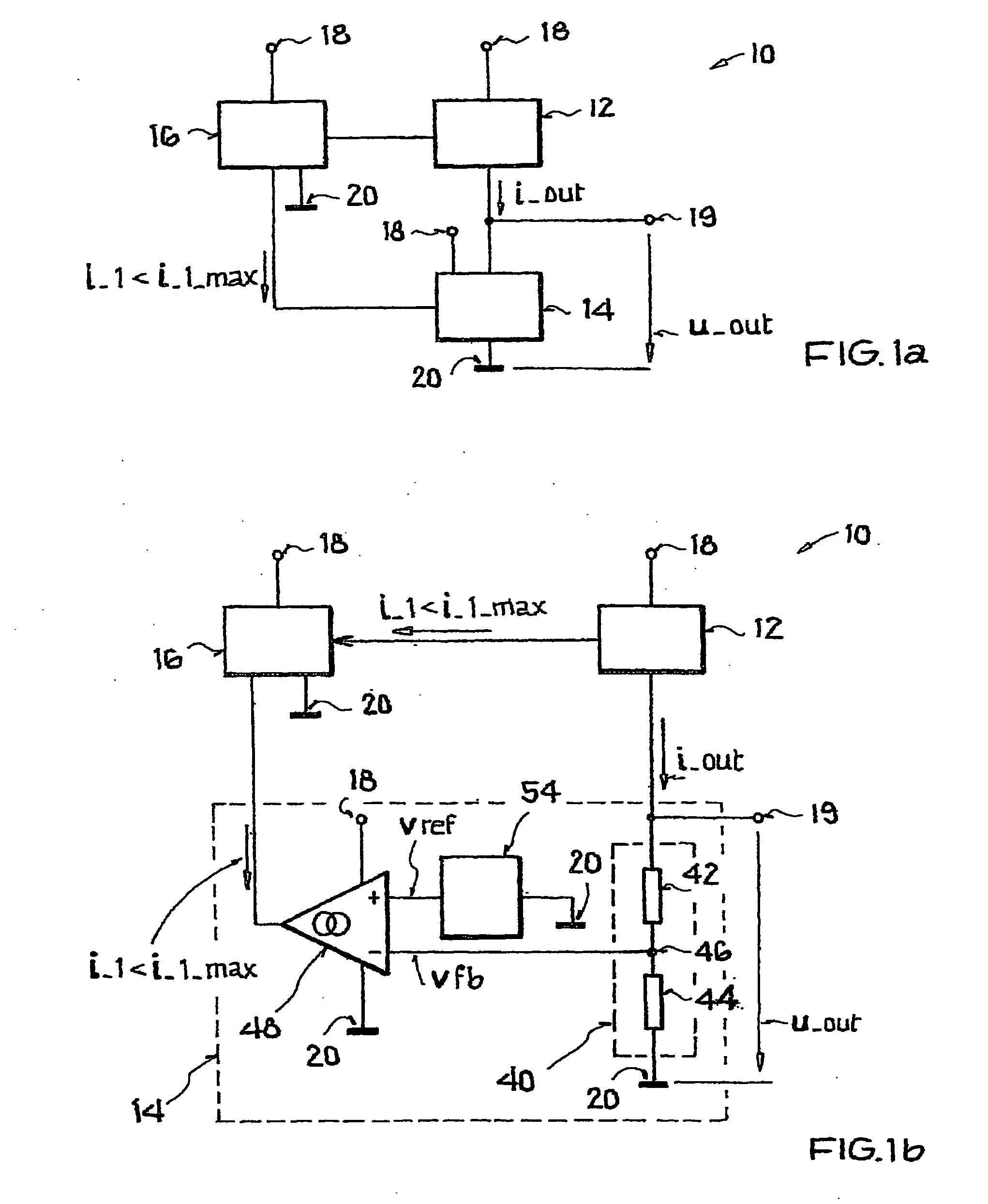
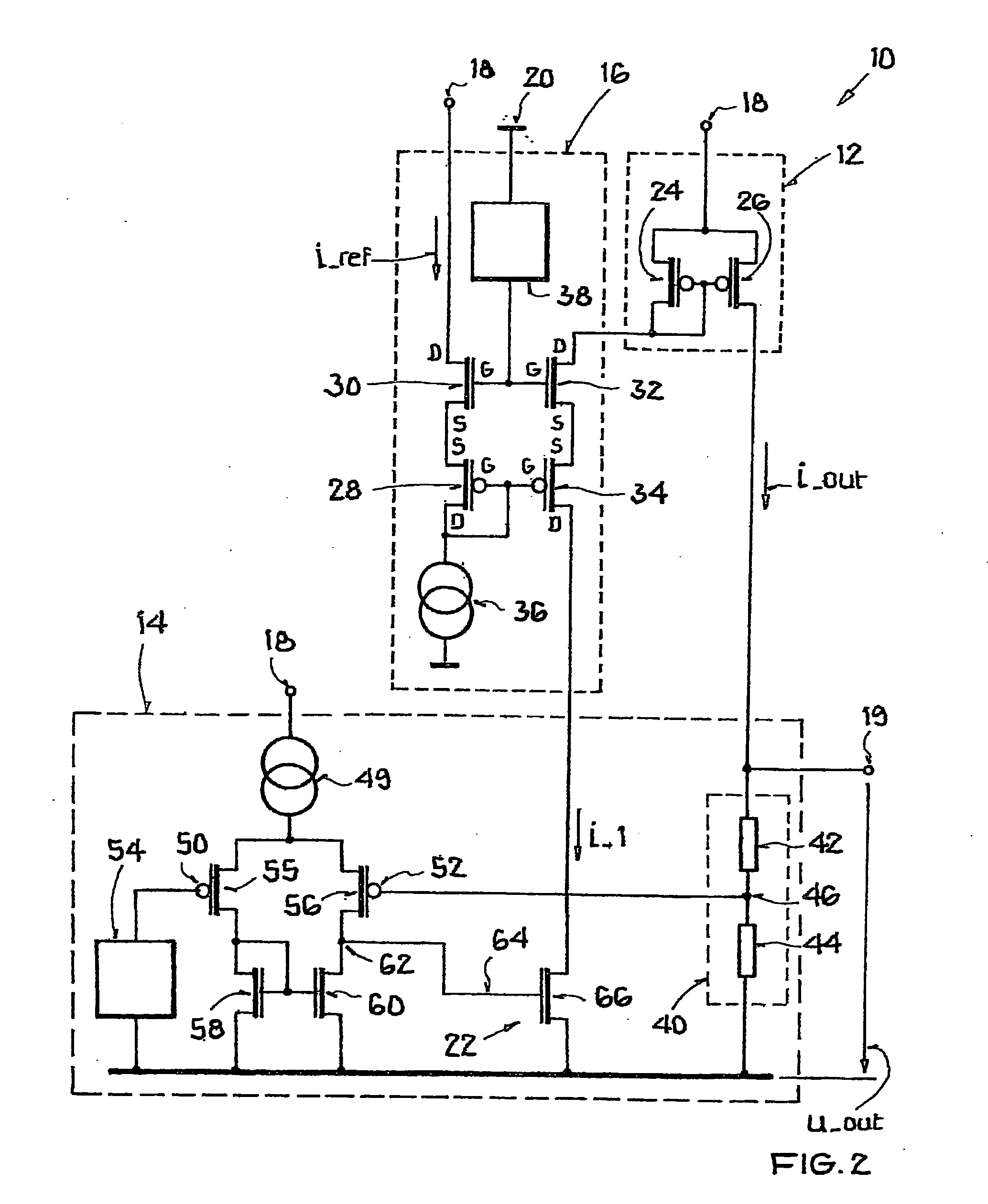
[0031]FIG. 1a shows in detail a constant voltage source 10 with an output current control element 12, a control circuit 14, and a limiting circuit 16. Constant voltage source 10 has supply potential terminals 18 and a reference potential terminal 20. Output current control element 12 outputs an output current i_out, which in the diagram of FIG. 1 flows across the control circuit 14 to reference potential 20. In this case, a voltage u_out drops across control circuit 14, which can be removed at an output voltage terminal 19. If a consumer is connected to output voltage terminal 19 and reference potential terminal 20, output current i_out divides into a partial current through the control circuit and a partial current through the consumer. To keep the output voltage constant at output voltage terminal 19, the partial current through control circuit 14 must generate substantially the same voltage drop there as without a connected consumer. To this end, output current i_out should be ac...


PUM


Abstract

A constant voltage source is disclosed having an output current control element, which adjusts an output voltage of the constant voltage source by varying its output current, a control circuit, which acquires a measure for an actual value of the output voltage and processes it to a control signal for the control of the output current control element, and a limiting circuit, which limits the output current to a predefined maximum value by action on the control signal, whereby the limitation is independent of an actual value of the output current. Wherein the limiting circuit has a first pair comprising a first transistor and a second transistor and a second pair comprising a third transistor and a fourth transistor, whereby the first and fourth transistor belong to a first conductivity type, the second and third transistor belong to a second conductivity type, operating current paths of the first pair lie in series between a reference current source and a supply potential, the operating current paths of the second pair are integrated in series into the control branch, control terminals of transistors of the same type are connected to one another, control terminals of transistors of the first conductivity type are connected to the reference current source, and control terminals of transistors of the second conductivity type to a first voltage source. Further, a method for generating a load-independent constant output voltage is disclosed.

Description

[0001] This nonprovisional application claims priority under 35 U.S.C. § 119(a) on German Patent Application No. DE 102005061377, which was filed in Germany on Dec. 13, 2005, and which is herein incorporated by reference. BACKGROUND OF THE INVENTION [0002] 1. Field of the Invention [0003] The present invention relates to a constant voltage source with an output current control element, which adjusts an output voltage (u_out) of the constant voltage source by varying its output current, with a control circuit, which determines an actual value of the output voltage and processes it to a control signal for controlling the output current control element, and with a limiting circuit, which limits the output current to a predefined maximum value by action on the control signal. Furthermore, the invention relates to a method for generating a load-independent constant output voltage with such a constant voltage source. [0004] 2. Description of the Background Art [0005] A constant voltage so...

Claims


Application Information

Patent Timeline
Patent Type & Authority Applications(United States)
IPC IPC(8): G05F3/16
CPCG05F1/575
Inventor HAUSER, CLEMENS
Owner ATMEL CORP
Why Eureka
Try Eureka