

Combination Electrical Stimulating And Infusion Medical Device and Method
- Summary
- Abstract
- Description
- Claims
- Application Information
AI Technical Summary
Benefits of technology
Problems solved by technology
Method used
Image

Examples
Embodiment Construction
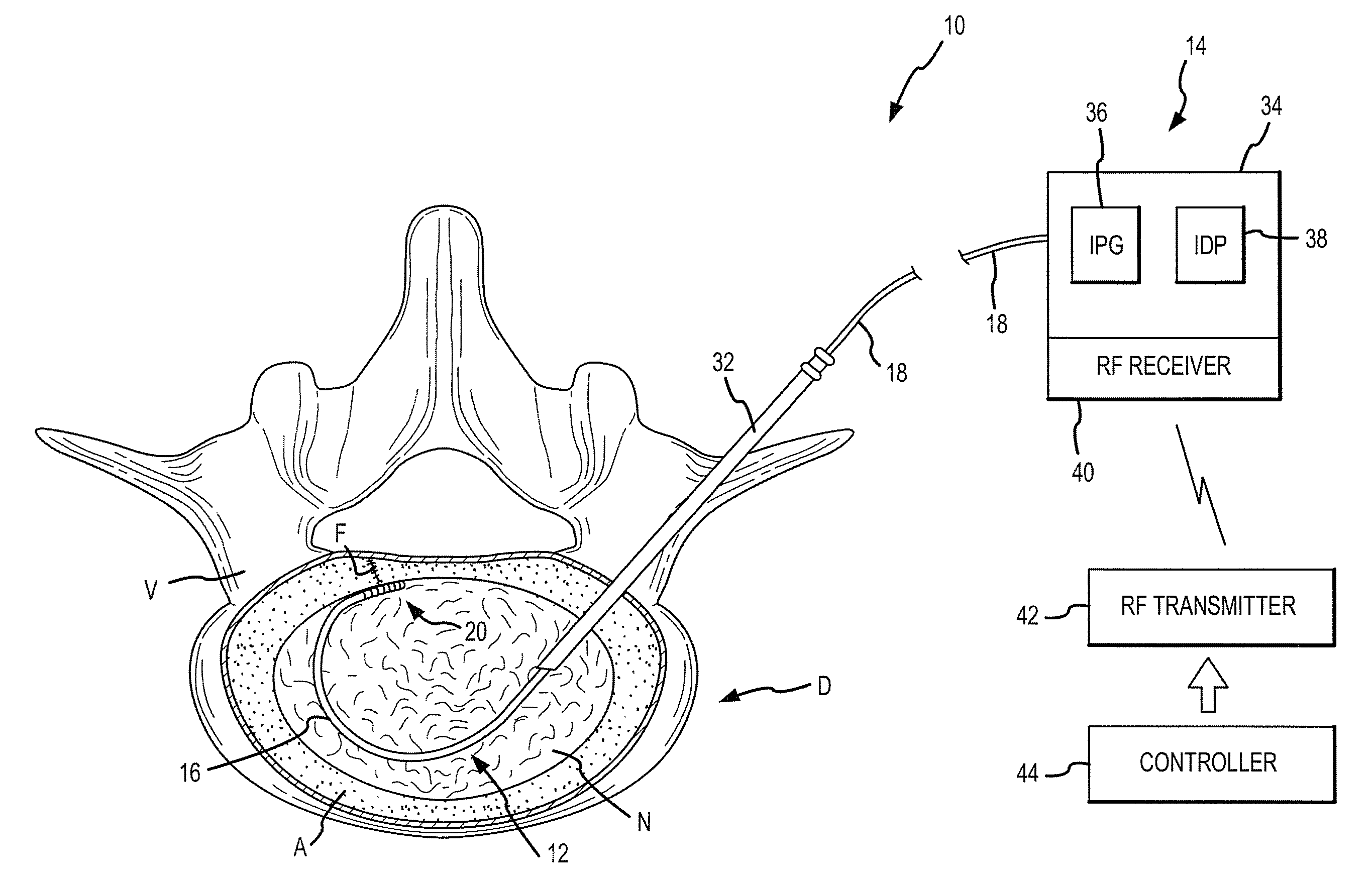
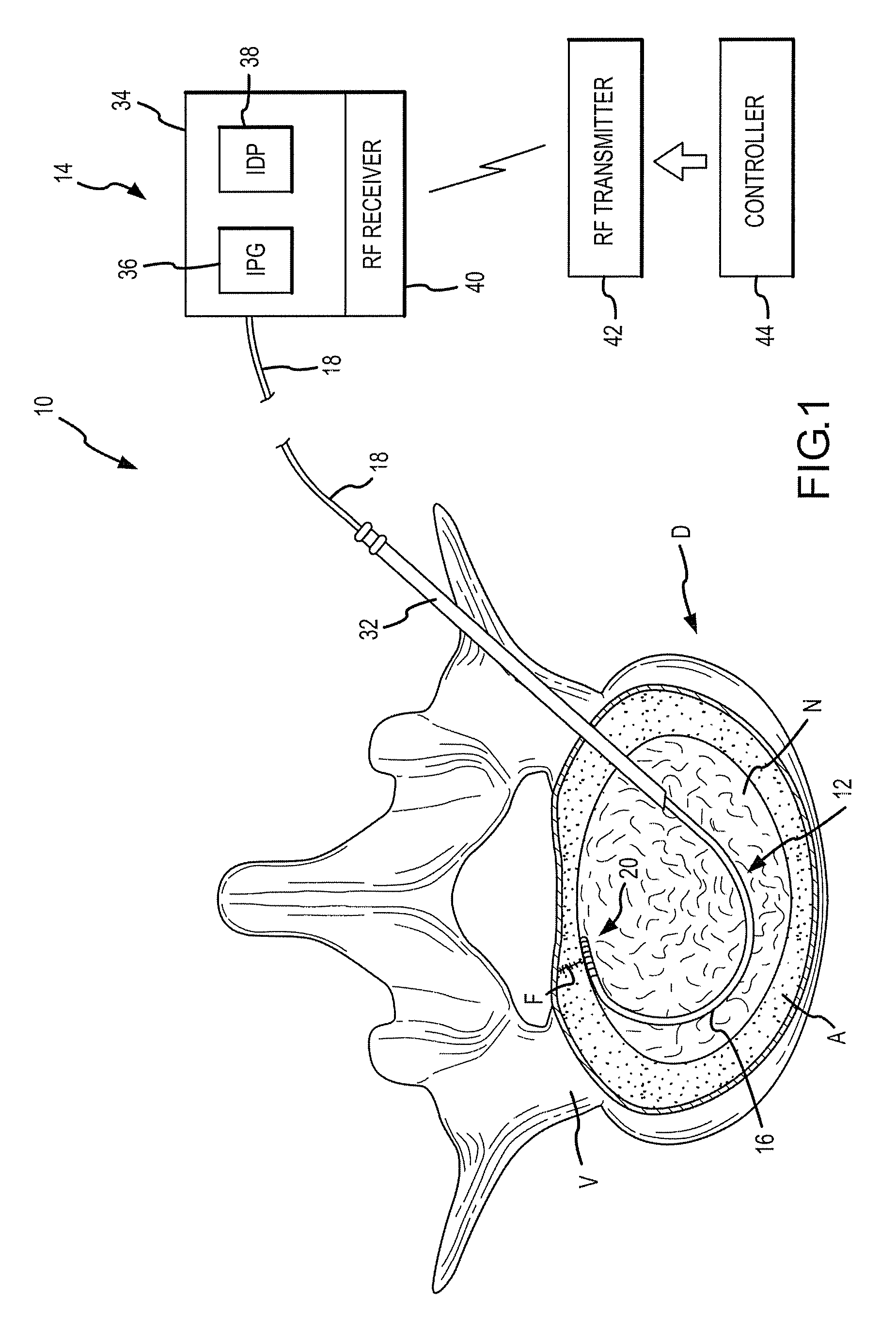
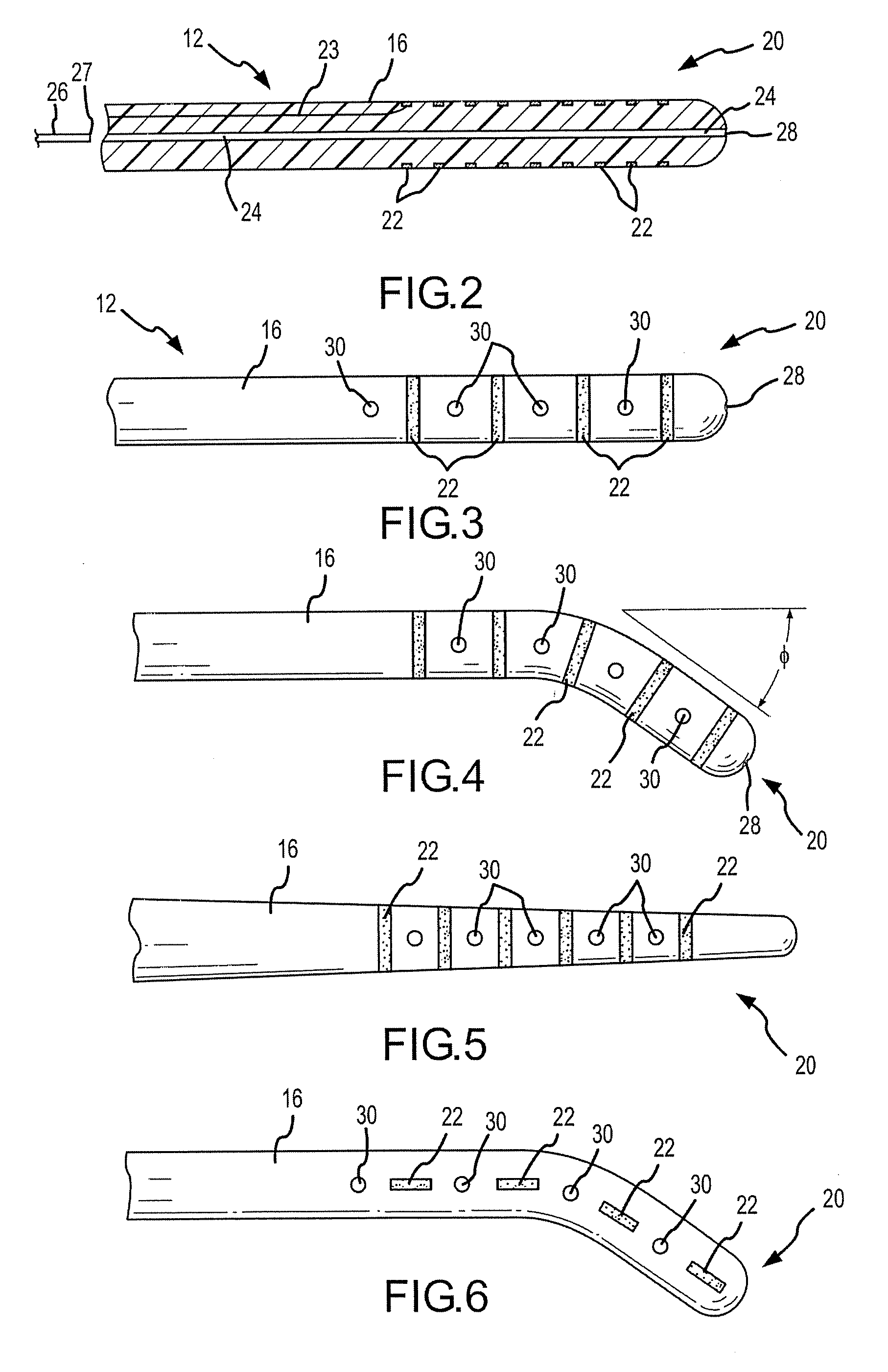
[0068] Referring to FIGS. 1 and 2, the system 10 of the present invention is shown that includes a combination electrical and chemical stimulation device 12, a stimulation source 14 that communicates with the stimulation device 12 for delivering electrical energy and chemicals to the stimulation device, and an interventional device such as an introducer needle 32 that allows introduction of the stimulation lead. The stimulation device 12 is shown as inserted within an intervertebral disc D. The combination device 12 more particularly includes a percutaneous electrical and chemical stimulation lead 16 in the form of an elongate tubular member having a desired length and diameter allowing the lead 16 to be placed within the intervertebral disc of the patient to be treated. The working distal portion 20 of the stimulation lead 16 provides the desired stimulation through a plurality of electrodes 22 which are selectively positioned on the distal portion 20, along with a plurality of inf...
PUM
 Abstract
Description
Claims
Application Information