
Hanger

a technology of hangers and hangers, applied in the field of hangers, can solve the problem of more space required to store or accommodate such hangers

Inactive Publication Date: 2007-07-12
KADO INDAL
View PDF16 Cites 33 Cited by
  • Summary
  • Abstract
  • Description
  • Claims
  • Application Information

AI Technical Summary

Problems solved by technology

However, given the relatively long distance between the extremities of the arms of the hangers, more space is required to store or accommodate such hangers, e.g. in a suitcase.

Method used


Image

  • Hanger
  • Hanger
  • Hanger

Examples


Embodiment Construction

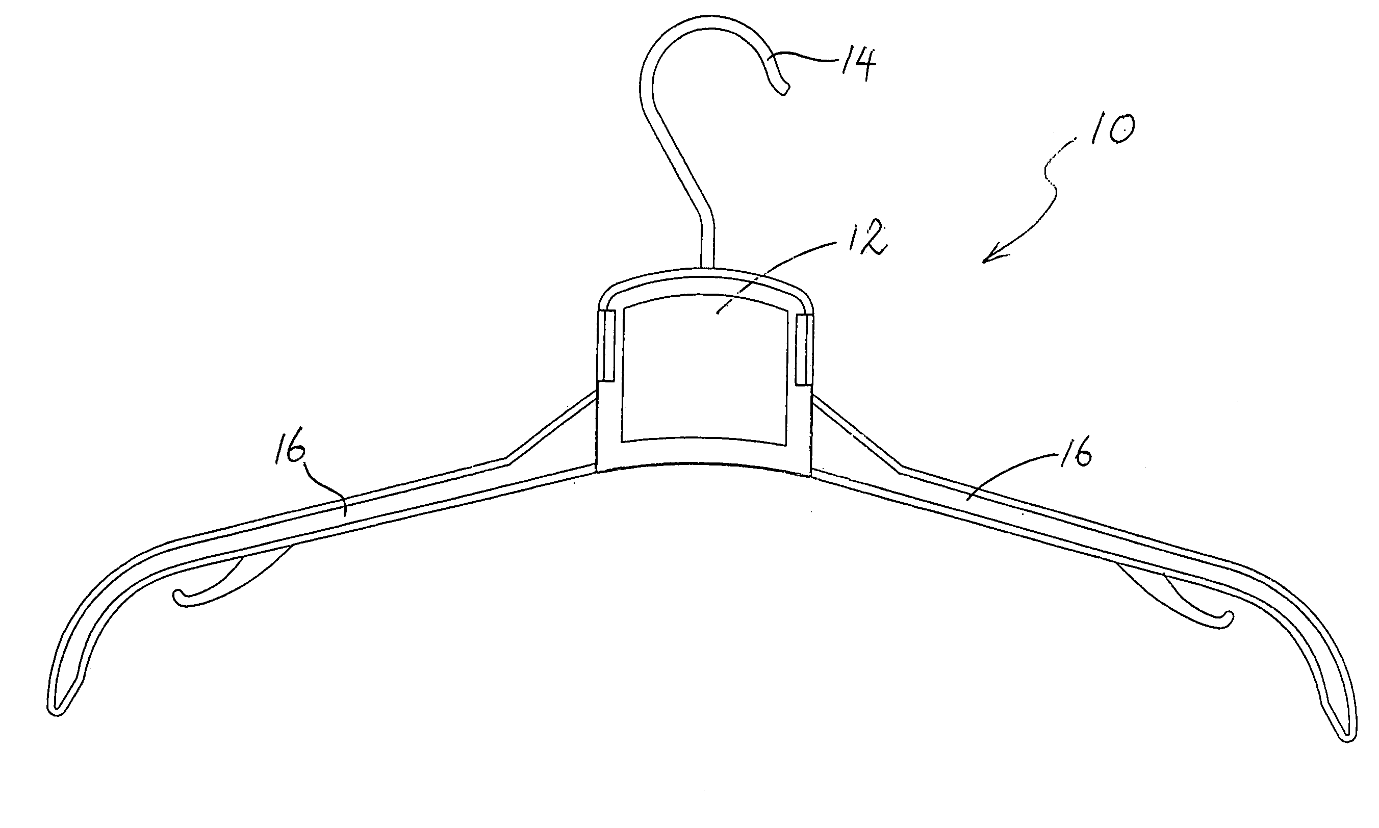
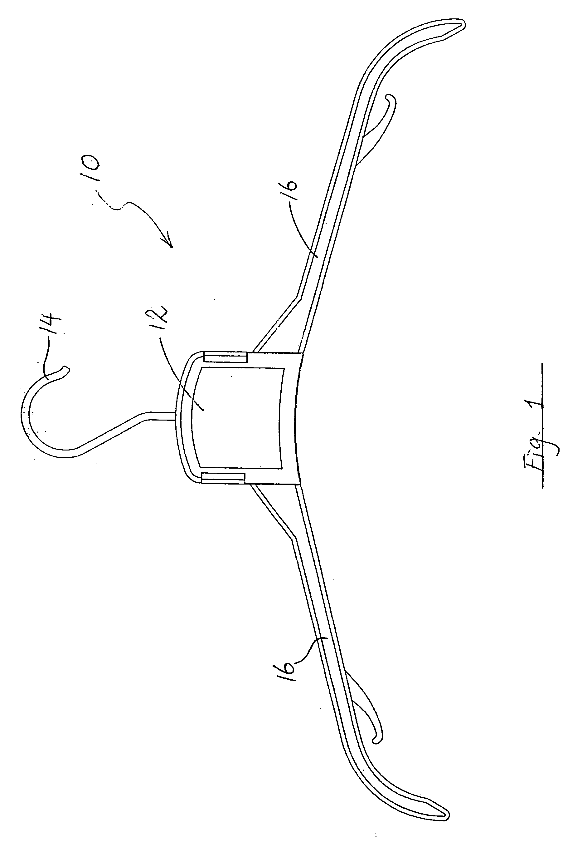
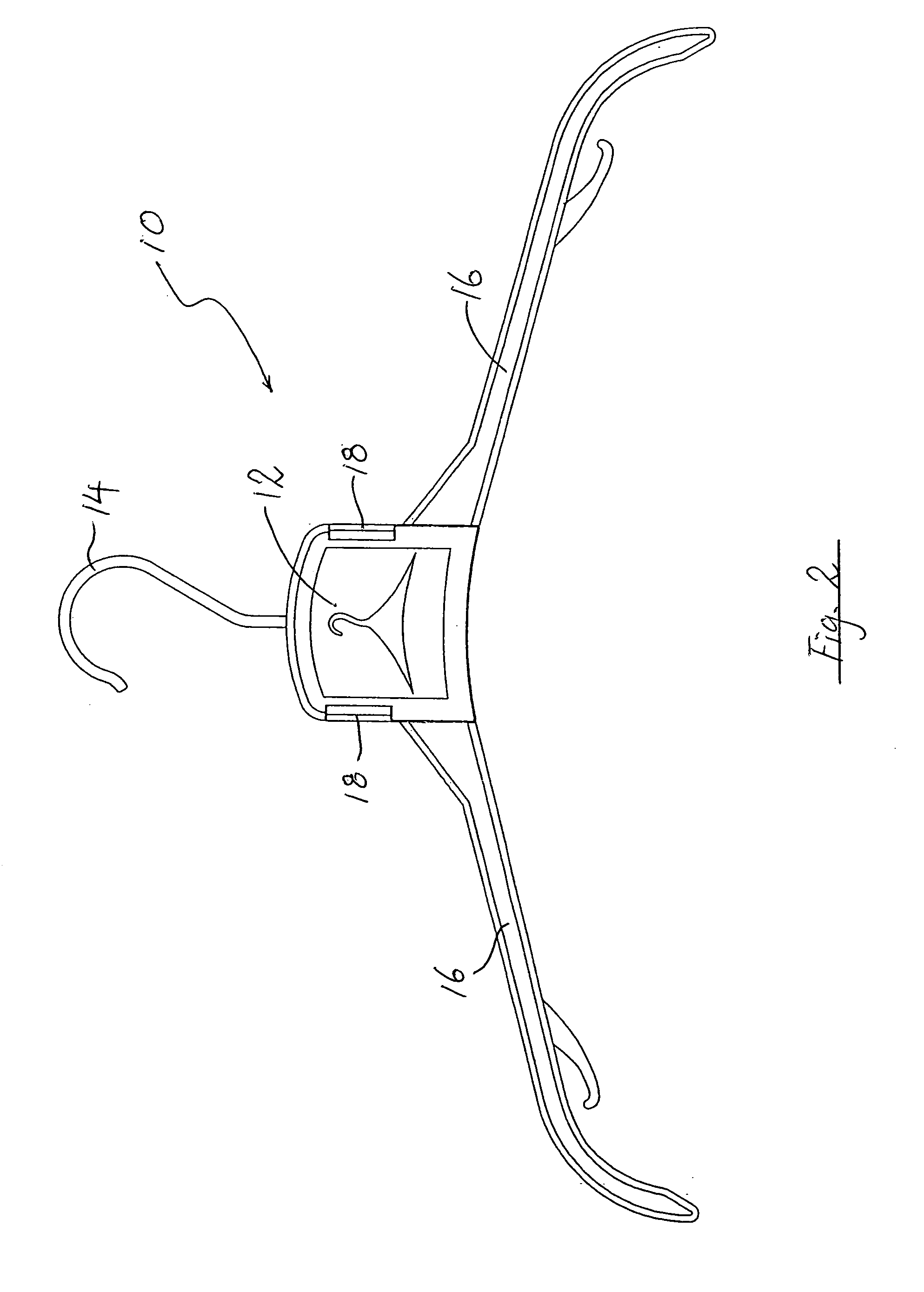
[0014] A hanger according to a preferred embodiment of the present invention is shown in FIGS. 1 and 2, and generally designated as 10. The hanger includes a central body part 12 from an upper end of which a hook 14 extends. Two arms 16 extend sideward from the body part 12, and a manually operable button 18 is engaged with each side of the body part12.

[0015] As shown in FIG. 3, the buttons 18 may be pressed from the outer position as shown in FIGS. 1 and 2 to the inner position as shown in FIG. 3 by an inwardly directing force F. When the buttons 18 are in the inwardly pressed position as shown in FIG. 3, the arms 16 may move, e.g. under gravity or be moved by a user, from the uppermost position as shown in FIG. 1, which may be referred to as the “in-use configuration”, to and remain in the intermediate position as shown in FIG. 4, and further to and remain in the lowermost position as shown in FIG. 5, which may be referred to as the “storage configuration”.

[0016] Turning now to ...


PUM


Abstract

A hanger for clothing item is disclosed as including a central body part, two locking members, and two arms in which the arms are swivellably movable relative to the body part between a lower position and an upper position, and the locking members are movable between a first position in which movement of the arms from the upper position to the lower position is prevented, and a second position in which movement of the arms from the upper position to the lower position is allowed.

Description

BACKGROUND OF THE INVENTION [0001] Hangers for clothing items have been available for a long time. Such hangers generally include a central body part with two arms extending leftward and rightward, and a hook extending generally upward. However, given the relatively long distance between the extremities of the arms of the hangers, more space is required to store or accommodate such hangers, e.g. in a suitcase. It is thus an objective of the present invention to provide a hanger in which such a shortcoming is mitigated or to provide at least a useful alternative to the trade and public. SUMMARY OF THE INVENTION [0002] According to the present invention, there is provided a hanger including a body member, at least one locking member, and two arm members wherein at least one said arm member is swivellably movable relative to said body member between a lower position and an upper position, wherein said at least one locking member is movable between a first position in which movement of ...

Claims


Application Information

Patent Timeline
Patent Type & Authority Applications(United States)
IPC IPC(8): A41D27/22
CPCA47G25/4023
Inventor CHAN, CHIK SUM
Owner KADO INDAL
Learn More