Floating drive on boat docking apparatus

a technology for boat docking and floating drive, which is applied in the direction of floating buildings, special-purpose vessels, transportation and packaging, etc., can solve the problems of difficult or impractical delivery, no additional mechanical advantage is employed by wilkins to augment, and the wilkins cannot achieve the effect of preventing the pivoting of the apparatus

Inactive Publication Date: 2007-07-26
BASTA IP INC
View PDF9 Cites 6 Cited by
  • Summary
  • Abstract
  • Description
  • Claims
  • Application Information

AI Technical Summary

Benefits of technology

[0011] The present invention is an improved floating boat lift incorporating a passive hydraulic pivoting lift mechanism, onto which a boat can be driven and positioned ready for storage using only the motive power of the boat itself. The passive hydraulic pivoting lift mechanism provides mechanical advantage in the pivoting action of the apparatus by way of passive hydraulic action, while at the same time dampening pivoting of the apparatus. Some embodiments further provide means for adjusting the elevation of the pivot point relative to the surface of the body of water by way of adjusting the buoyancy of the pivoting lift mechanism.

Problems solved by technology

Floating upon the body of water, such lifts provide convenient dry docking at a constant level above the surface, in contrast with fixed lifts whose use may at times be rendered difficult or impractical due to varying seasonal depth of the body of water.
Floating lifts can provide dry docking in bodies of water in which securing a fixed boat lift is difficult, as in deep muddy or sandy bottoms.
Second, no additional mechanical advantage is employed by Wilkins to augment the leverage provided by the change in weight distribution caused by receipt of the boat.
Third, Wilkins does not provide a damping functionality for his tilting apparatus: in embodiments relying on change in weight distribution to effect tilting, as the apparatus is tilted to elevate the boat and the center of gravity of the mechanism passes over-center of the pivot point, the lift apparatus settles to the elevated position in an abrupt fashion which can be jarring for the boat operator and tends to cause wear and fatigue of the lift mechanism.

Method used


Image

  • Floating drive on boat docking apparatus
  • Floating drive on boat docking apparatus
  • Floating drive on boat docking apparatus

Examples


Embodiment Construction

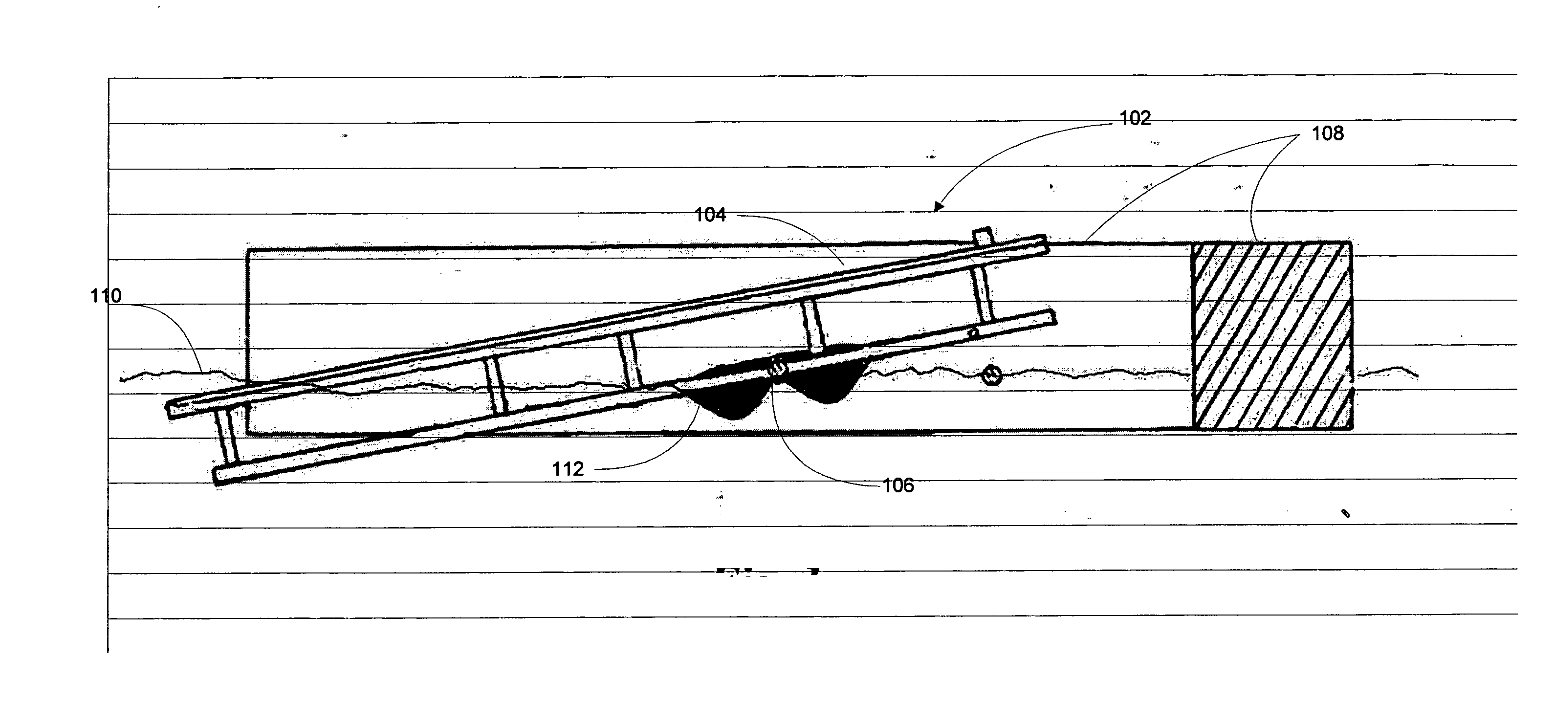
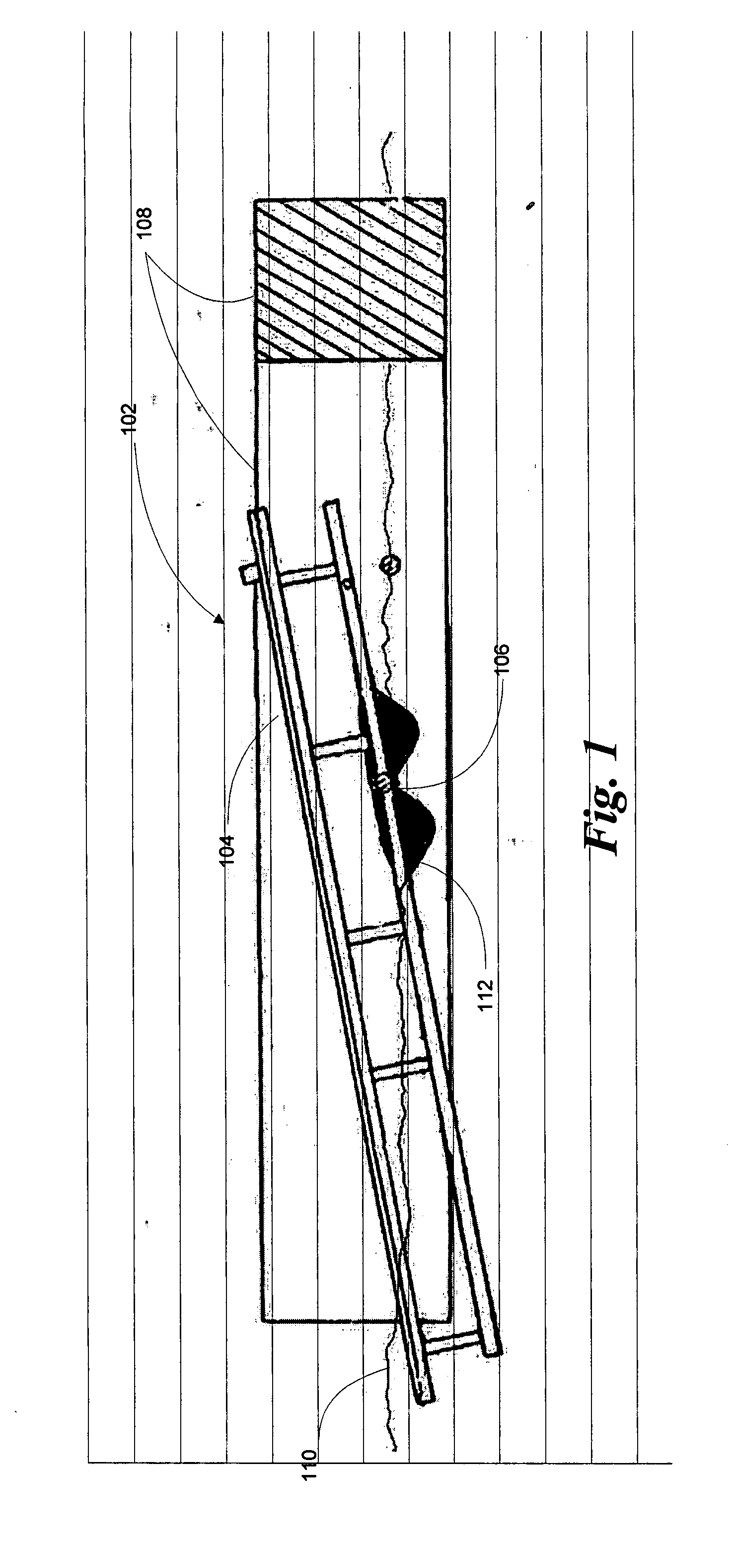
[0019] Turning to FIG. 1, illustrated is a floating boat lift 102, positioned for receipt of a boat, comprised of a frame 104, pivoting about a pivot point 106 which is buoyantly suspended by floating means 108 floating upon the surface 110 of a body of water. As is known to those in the art, floating means 108 may comprise a well formed by conjoined floating dock segments. Alternatively, floating means 108 my comprise pontoons specifically fashioned for the purpose of providing flotation for the lift. In any case, as will become clear from examination of the subsequent drawings, the lifting functionality of such floating boat lifts derives from the ability of the frame to pivot about a buoyantly suspended pivot point. Improving upon the prior art, the present invention further provides a passive hydraulic contrivance 112, affixed to and pivoting with the frame.

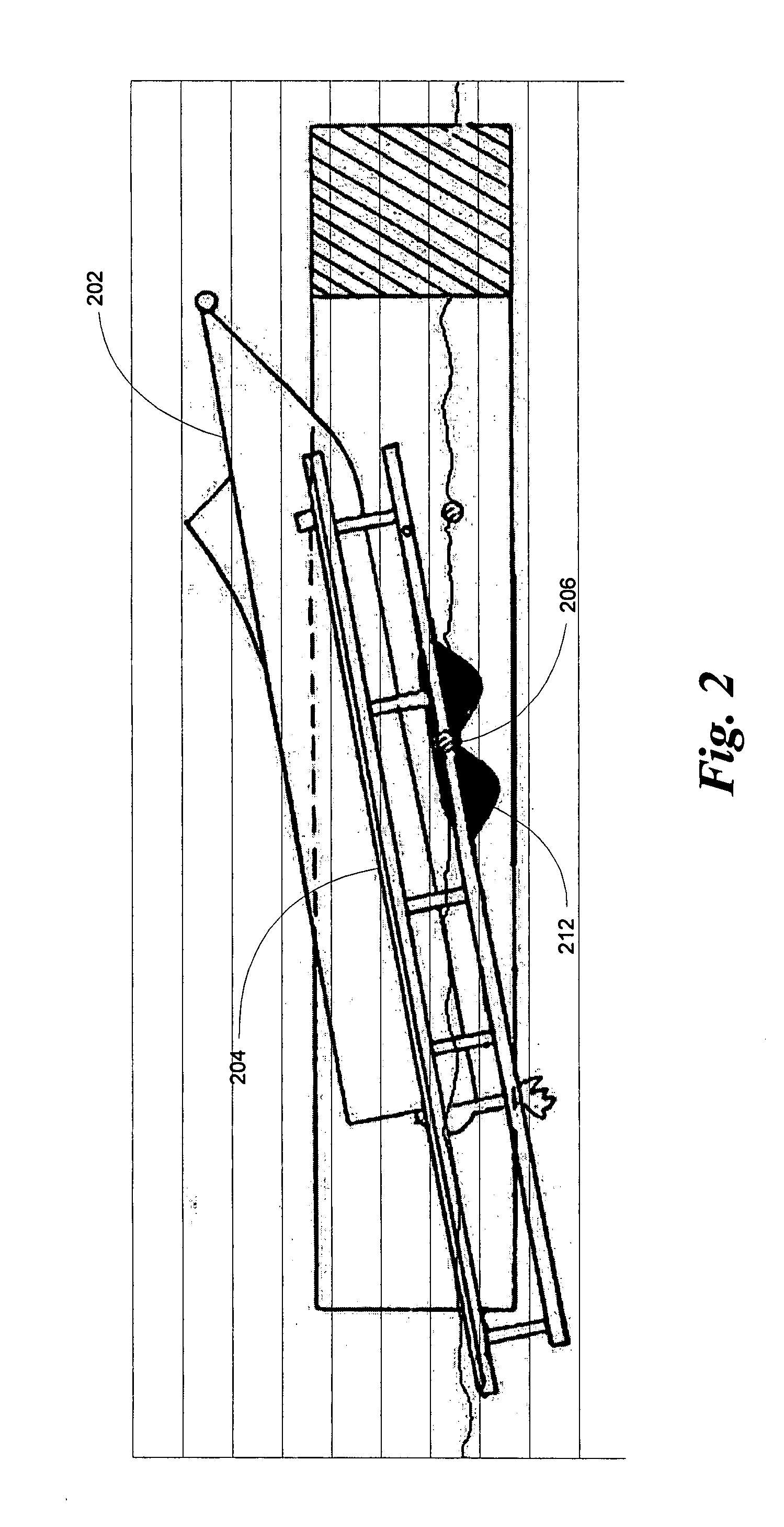
[0020] Turning now to FIG.2, illustrated is the lift immediately after a boat 202 has been driven onto it under its own mo...


PUM


Abstract

An improved floating boat lift incorporates a passive hydraulic pivoting lift mechanism, onto which a boat can be driven and positioned ready for storage using only the motive power of the boat itself. The passive hydraulic pivoting lift mechanism provides mechanical advantage in the pivoting action of the apparatus by way of passive hydraulic action, while at the same time dampening pivoting of the apparatus. Embodiments further provide means for adjusting the elevation of the pivot point relative to the surface of the body of water by way of adjusting the buoyancy of the pivoting lift mechanism.

Description

[0001] This application is a continuation of U.S. patent application Ser. No. 11 / 324,010, filed 31 Dec. 2005, which application is incorporated herein by reference.FIELD OF THE INVENTION [0002] This invention relates to an improvement in floating boat lift apparatus. BACKGROUND OF INVENTION [0003] Various apparatus have been devised for dry-docking boats. Pleasure boats of the kind to which the present invention is particularly adapted are thought of, for purpose of the present description, as being generally within the range of about fifteen feet to twenty-four feet in length and within the range of about 800 pounds to 6000 pounds in weight. Apparatus for docking pleasure boats has been associated with both non-floating as well as floating docks. The use of such apparatus is intended to facilitate removal of a boat from the water, maintaining the boat in a stored position elevated above the water, and for launching of the boat into the water. [0004] Among the many methods known and...

Claims


Application Information

Patent Timeline
Patent Type & Authority Applications(United States)
IPC IPC(8): B63C1/02
CPCB63C3/02
Inventor BASTA, SAMUEL T.
Owner BASTA IP INC
Why Eureka
Try Eureka