Spinous process fixation implant

a technology of fixation implant and process, which is applied in the field of system and method of spinal stabilization through an implant, can solve the problems of increasing the amount of blood loss, difficult to maintain a clear operative field, and the difficulty of the rod fixation system to extend to the higher or lower levels that need to be fused, etc., and achieves the effect of stabilizing the vertebra

Active Publication Date: 2007-08-02
KIC VENTURES LLC +1
View PDF26 Cites 155 Cited by
  • Summary
  • Abstract
  • Description
  • Claims
  • Application Information

AI Technical Summary

Benefits of technology

[0010] Among the advantages of this invention may be one or more of the following. The assembly stabilizes vertebras by attaching plates to the spinous processes of the vertebras. This stabilization device does not add bulk to the lateral aspect of the spine and does not limit access to the pars and transverse processes for decortication and placement of bone graft.

Problems solved by technology

In order to avoid this limitation many surgeons decorticate before placing the rods, thereby increasing the amount of blood loss and making it more difficult to maintain a clear operative field.
In situations where problems develop at the junction above or below the fused segments necessitating additional fusion, the rod fixation system is difficult to extend to higher or lower levels that need to be fused.
Although there are connectors and techniques to lengthen the fixation, they tend to be difficult to use and time consuming.

Method used


Image

  • Spinous process fixation implant
  • Spinous process fixation implant
  • Spinous process fixation implant

Examples


second embodiment

[0056] Referring to FIG. 15, FIG. 16, FIG. 17, FIG. 18, in the spinous process fixation assembly 200, the top and bottom pivoting plates 220, 230 are designed to pivot past each other and to form any angle with the elongated plate 210 between 0 and 180 degrees. In particular, plates 220 and 230 pivot to a 90 degree angle relative to plate 210 and form a sidewise oriented T, shown in FIG. 16 and FIG. 180. The assembly 200 of FIG. 16, with the pivoting plates 220, 230 at a 90 degree angle with the plate 110, is inserted sidewise between the top and bottom spinous processes 90a, 90b. Once the assembly is inserted, the plates 220 and 230 are pivoted upward and downward, respectively, and are placed at angles relative to the plate 210 necessary to provide the desired fit of the plates to the spinous processes. Sidewise implantation of the assembly 200 has the advantage of reduced trauma in the area between the spinous processes.

[0057] In this embodiment the top pivoting plate 220 has a m...

third embodiment

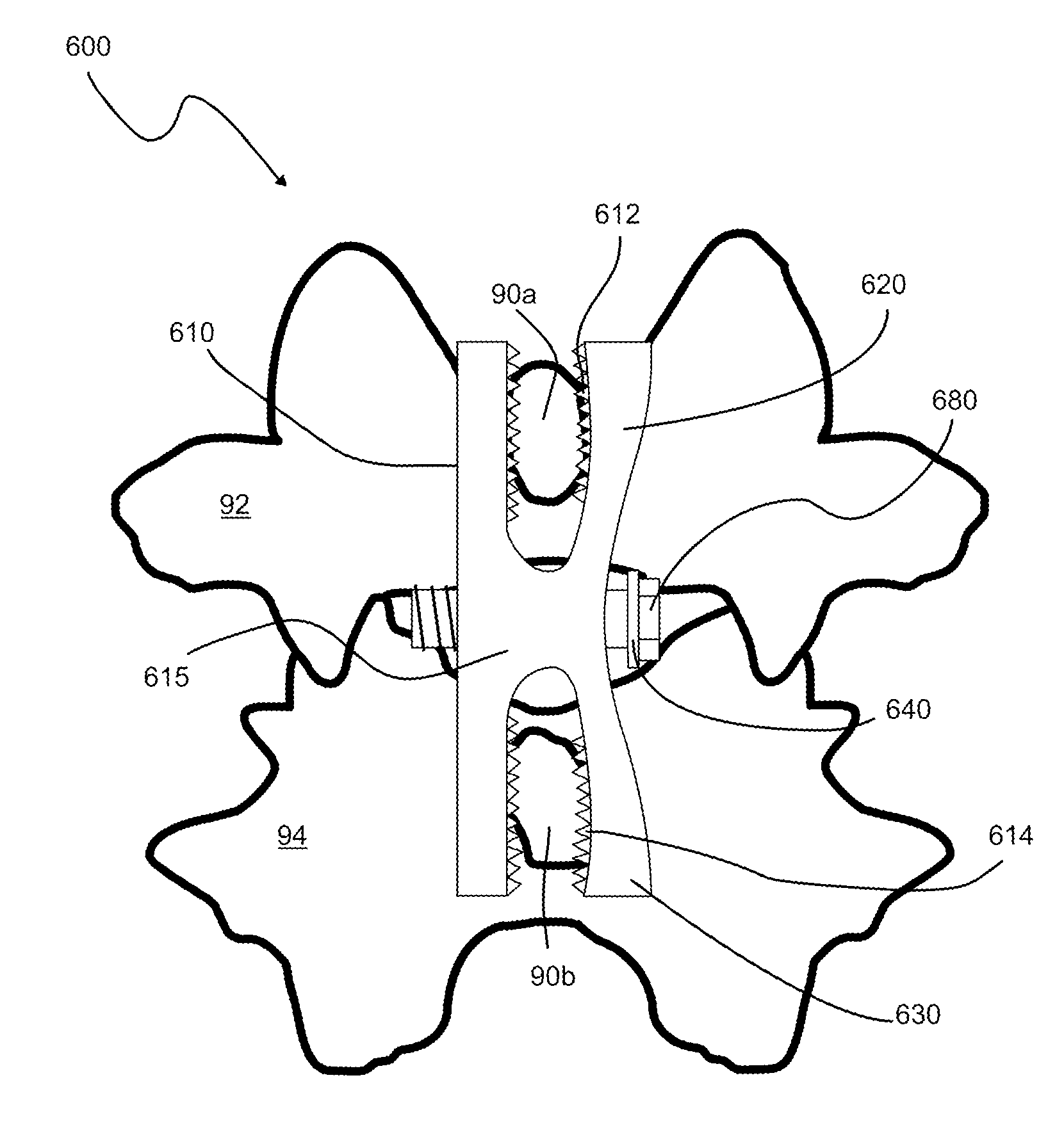
[0059] Referring to FIG. 21, in a third embodiment the spinous process fixation assembly 300 includes a front S-shaped plate 310 and a mirror image back S-shaped plate 320 connected at their centers via a bolt 380 forming an X-shaped structure. The front S-shaped plate 310 pivots relative to a back S-shaped plate 320 around pivot point 340 and the spinous process 90a of the top vertebra 92 is frictionally engaged between the upper arms of S-plates 310 and 320, while the spinous process 90b of the bottom vertebra 42 is frictionally engaged between the lower arms of S-plates 310 and 320. A bolt 380 is threaded through apertures formed in the centers of the front and back S-plates, as shown in FIG. 21. The inner surfaces of the upper and lower arms of the S-shaped plates are sculpted to fit the shape of the spinous processes and have protrusions that frictionally engage the sides of the spinous processes and together with the bolt 380 securely lock the assembly 300 between the spinous ...

embodiment 500

[0063] Long bolts 370 may be also added to this embodiment to further anchor the assembly 400 on the spinous processes, as was described above. Alternatively, a staple 450 may be placed on the top and bottom open ends of the plates 410, 420 and 430, as shown in FIG. 27. In other embodiments banding, cabling or suturing may be used to attach the ends of plates 410, 420 and 430 to the spinous processes. The outer surfaces of the plates 410, 420 and 430 may be rounded, as shown in FIG. 24 or straight, a shown in the embodiment 500 of FIG. 27.

[0064] Referring to FIG. 28, FIG. 29 and FIG. 30, the process of implanting the spinous process fixation assembly between two adjacent vertebrae includes the following steps. First an incision is made in the patient's back and paths A and B are opened along bony planes 95 and through ligaments96 between the adjacent spinous processes 90a, 90b. Path B is mirror image of path A about the centered sagittal plane 98. Next, the back component 510 of the...


PUM


Abstract

An implantable spinous process fixation device includes a k-shaped component comprising an elongated plate and top and bottom deformable plates extending at first and second angles from a first surface of the elongated plate, respectively, thereby defining first and second spaces between the elongated plate and the top and bottom deformable plates and a compression element configured to compress and move the first and second deformable plates toward the elongated plate and to change the first and the second angles, respectively. The first and second spaces are configured to receive first and second spinous processes, respectively. Compressing and moving the first and second deformable plates toward the elongated plate results in engaging the first surface of the elongated plate and first surfaces of the top and bottom deformable plates with lateral surfaces of the first and second spinous processes, respectively.

Description

CROSS REFERENCE TO RELATED CO-PENDING APPLICATIONS [0001] This application claims the benefit of U.S. provisional application Ser. No. 60 / 750,520 filed Dec. 14, 2005 and entitled “SPINOUS PROCESS FIXATION IMPLANT”, the contents of which are expressly incorporated herein by reference. [0002] This application is also a continuation of U.S. application Ser. No. 11 / 609,418 filed on Dec. 12, 2006 and entitled SPINOUS PROCESS FIXATION IMPLANT the contents of which are expressly incorporated herein by reference.FIELD OF THE INVENTION [0003] The present invention relates to a system and a method for spinal stabilization through an implant, and more particularly to spinal stabilization through attachment of the implant to the spinous processes along one or more vertebras. BACKGROUND OF THE INVENTION [0004] The human spine comprises individual vertebras 30 (segments) that are connected to each other to form a spinal column 29, shown in FIG. 1. Referring to FIGS. 1B and 1C, each vertebra 30 ha...

Claims


Application Information

Patent Timeline
Patent Type & Authority Applications(United States)
IPC IPC(8): A61F2/30
CPCA61B17/7065A61B17/7068
Inventor CHIN, KINGSLEY R.BAKER, DANIEL R.JUSTIN, DANIEL F.
Owner KIC VENTURES LLC
Why Eureka
Try Eureka