Spinous process fixation implant

a technology of spinal cord and fixation system, which is applied in the field of system and method of spinal stabilization through an implant, can solve the problems of increasing the amount of blood loss, difficult to maintain a clear operative field, and the difficulty of extending the rod fixation system to the higher or lower level that needs to be fused, etc., and achieves the effect of stabilizing the vertebrae and promoting bone growth through the devi

Active Publication Date: 2010-04-08
KIC VENTURES LLC
View PDF23 Cites 110 Cited by
  • Summary
  • Abstract
  • Description
  • Claims
  • Application Information

AI Technical Summary

Benefits of technology

[0010]Among the advantages of this invention may be one or more of the following. The assembly stabilizes vertebras by attaching components to the spinous processes of the vertebras. This stabilization device does not add bulk to the lateral aspect of the spine and does not limit access to the pars and transverse processes for decortication and placement of bone graft. The compact form of the implant assembly allows it to be implanted via mini-open surgery. The device form conforms to the local vertebral anatomy. In particular, the adjustable winged plates fit to the spinous process contour. The device may be used alone or as adjunct to facet or pedicle screw systems. It provides multi-level (i.e., multi-vertebra) fusion through replication of the basic unit. The device is securely attached to the spinous processes via the center post, individual wings and pins. The fenestrated spacer enables application of graft material and promotes bone growth through the device.

Problems solved by technology

In order to avoid this limitation many surgeons decorticate before placing the rods, thereby increasing the amount of blood loss and making it more difficult to maintain a clear operative field.
In situations where problems develop at the junction above or below the fused segments necessitating additional fusion, the rod fixation system is difficult to extend to higher or lower levels that need to be fused.
Although there are connectors and techniques to lengthen the fixation, they tend to be difficult to use and time consuming.

Method used


Image

  • Spinous process fixation implant
  • Spinous process fixation implant
  • Spinous process fixation implant

Examples


Embodiment Construction

[0041]The present invention relates to a system and a method for an improved spinous process fixation implant.

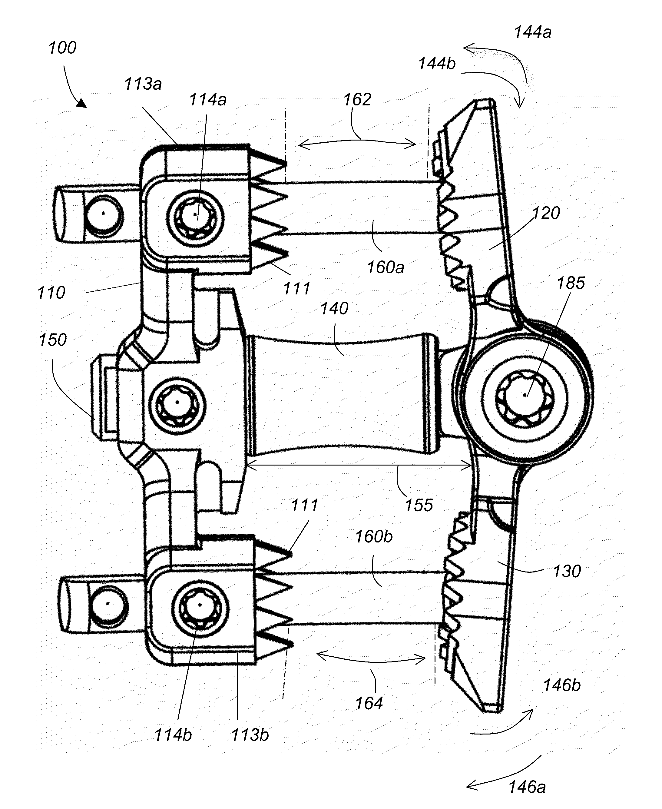
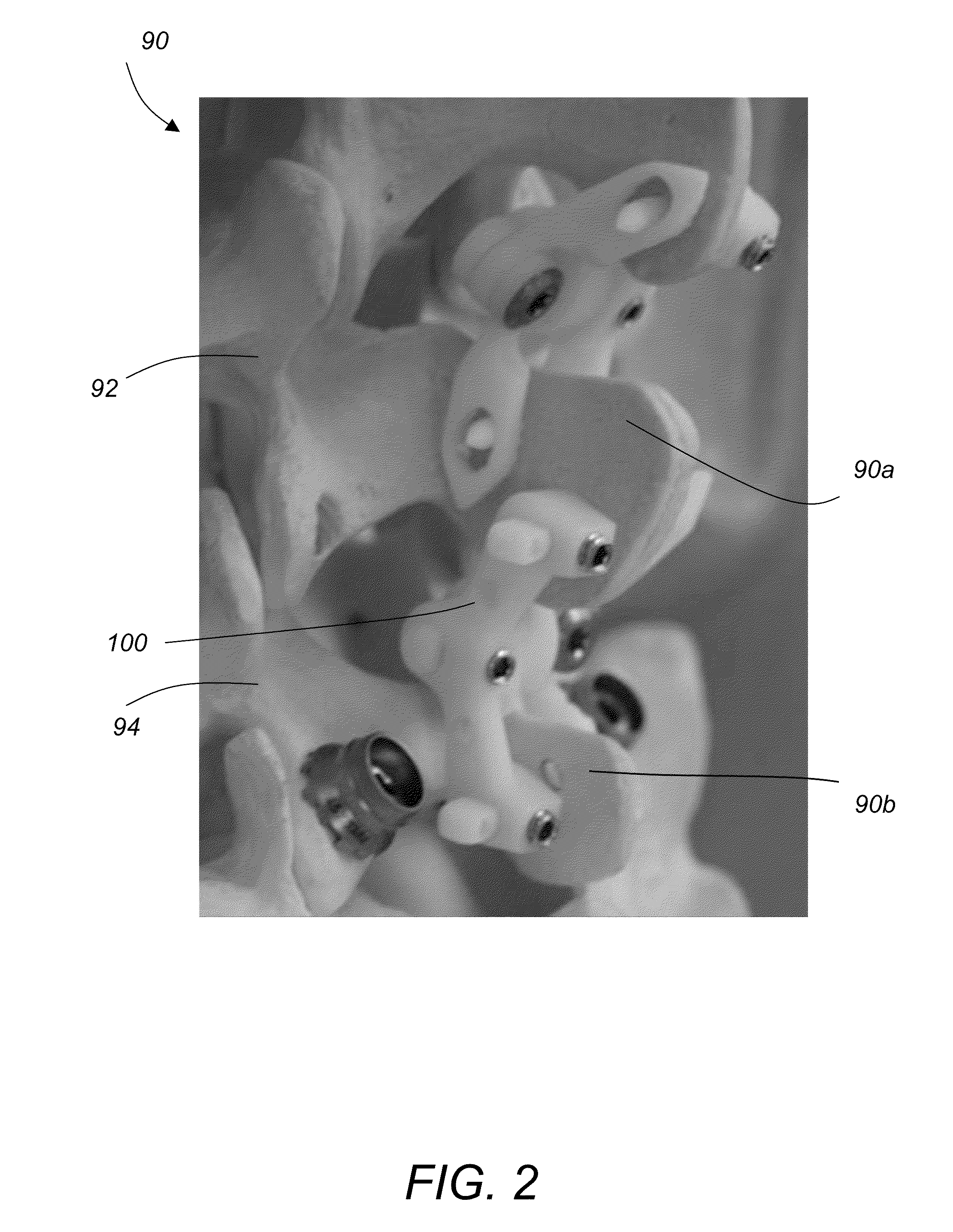
[0042]Referring to FIG. 2, spinous process fixation assembly 100 stabilizes two adjacent vertebras 92, 94 of the human spine by engaging and locking their spinous processes 90a and 90b, respectively. Referring to FIG. 3, spinous process fixation assembly 100 includes an elongate component 110, top and a bottom pivoting wing components 120, 130 and a spacer 140. Top and bottom pivoting wing components 120, 130 are arranged opposite to component 110 at a distance 155 set by the length of spacer 140. Top and bottom pivoting wing components 120, 130 pivot around axis 180 (shown in FIG. 6) independent from each other, forming angles 162, 164 with component 110, respectively. The pivoting motion of components 120, 130 along directions 144a, 144b and 146a, 146b, moves them close to or away from the elongated component 110, as shown in FIG. 3 and results in clamping or unclamping of...


PUM


Abstract

An implantable spinous process fixation device includes an elongated component, top and bottom pivoting wing components, arranged opposite and parallel to the elongated component and separated from it by a spacer. First and second spinous processes of first and second adjacent vertebras are clamped between a top portion of the elongated component and the top pivoting wing and between a bottom portion of the elongated component and the bottom pivoting wing, respectively, by pivoting the top and bottom pivoting wings toward the top and bottom portions of the elongated component. The clamping of the spinous processes stabilizes the positions of the adjacent vertebras and prevents them from moving relative to each other.

Description

CROSS REFERENCE TO RELATED CO-PENDING APPLICATIONS[0001]This application claims the benefit of U.S. provisional application Ser. No. 61 / 121,955 filed Dec. 12, 2008 and entitled “IMPROVED SPINOUS PROCESS FIXATION IMPLANT”, the contents of which are expressly incorporated herein by reference.[0002]This application is also a continuation in part of U.S. utility application Ser. No. 11 / 609,418 filed Dec. 12, 2006 and entitled “SPINOUS PROCESS FIXATION IMPLANT”, the contents of which are expressly incorporated herein by reference.FIELD OF THE INVENTION[0003]The present invention relates to a system and a method for spinal stabilization through an implant, and more particularly to spinal stabilization through attachment of an improved implant to the spinous processes along one or more vertebras.BACKGROUND OF THE INVENTION[0004]The human spine comprises individual vertebras 30 (segments) that are connected to each other to form a spinal column 29, shown in FIG. 1. Referring to FIGS. 1B and...

Claims


Application Information

Patent Timeline
Patent Type & Authority Applications(United States)
IPC IPC(8): A61B17/70A61B17/88
CPCA61B17/7065A61B17/1671
Inventor CHIN, KINGSLEY R.REIF, CHRISTINECORRAO, ERNIESAUNDERS, TODD
Owner KIC VENTURES LLC
Why Eureka
Try Eureka