Spinous process fixation device

a technology of fixation device and process, which is applied in the field of system and method of spinal stabilization through an implant, can solve the problems of increasing the amount of blood loss, difficult to maintain a clear operation field, and the difficulty of the rod fixation system to extend to the higher or lower levels that need to be fused, etc., and achieves the effect of stabilizing the vertebra

Active Publication Date: 2011-01-18
KIC VENTURES LLC +1
View PDF4 Cites 140 Cited by
  • Summary
  • Abstract
  • Description
  • Claims
  • Application Information

AI Technical Summary

Benefits of technology

[0010]Among the advantages of this invention may be one or more of the following. The assembly stabilizes vertebras by attaching plates to the spinous processes of the vertebras. This stabilization device does not add bulk to the lateral aspect of the spine and does not limit access to the pars and transverse processes for decortication and placement of bone graft.

Problems solved by technology

In order to avoid this limitation many surgeons decorticate before placing the rods, thereby increasing the amount of blood loss and making it more difficult to maintain a clear operative field.
In situations where problems develop at the junction above or below the fused segments necessitating additional fusion, the rod fixation system is difficult to extend to higher or lower levels that need to be fused.
Although there are connectors and techniques to lengthen the fixation, they tend to be difficult to use and time consuming.

Method used


Image

  • Spinous process fixation device
  • Spinous process fixation device
  • Spinous process fixation device

Examples


Embodiment Construction

[0027]The present invention relates to a system and a method for a spinous process fixation implant.

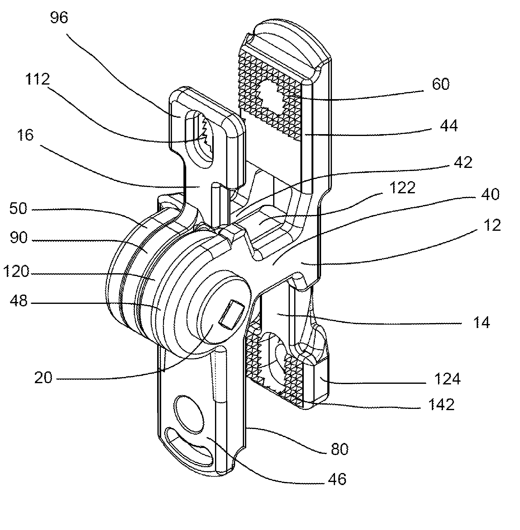
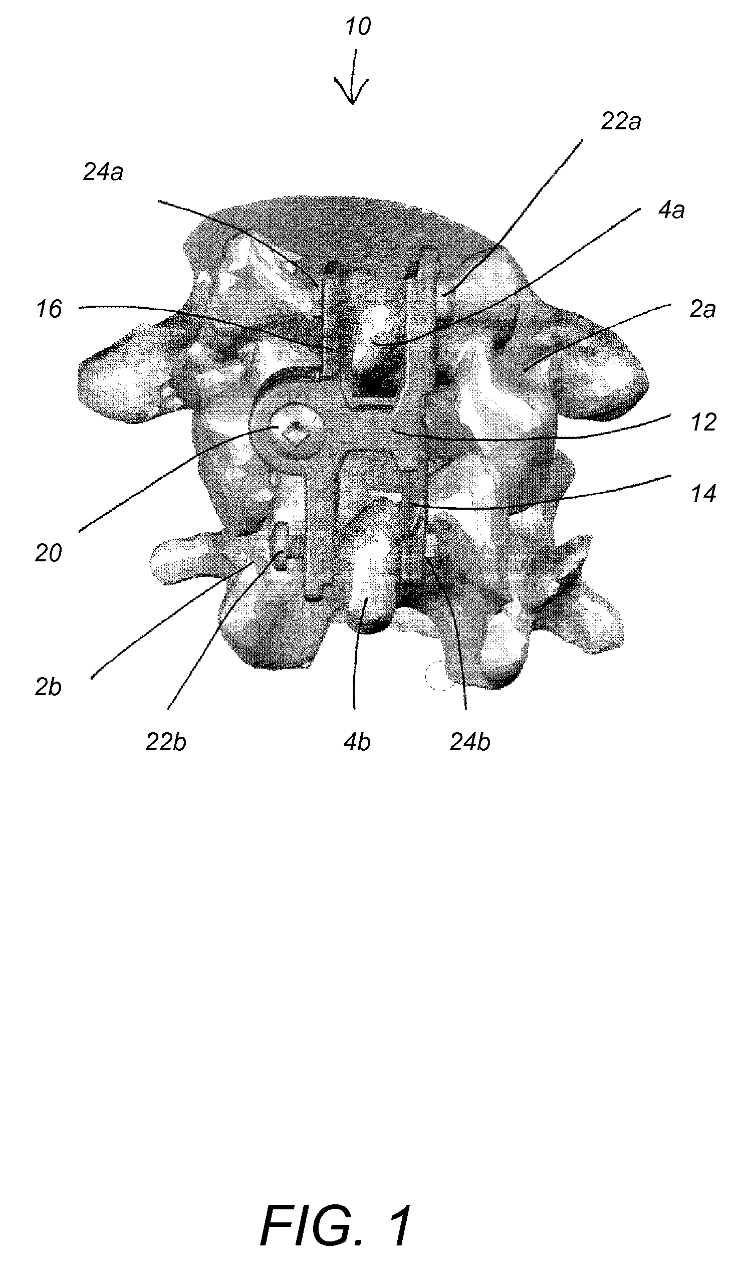
[0028]Referring to FIG. 1, a posterior view illustrates a portion of the spine with an embodiment of the present invention. A spinous process fixation device 10 includes a body 12, a bent arm 14, and a straight arm 16. A short bolt 20, two long bolts 22a, 22b, and nuts 24a, 24b hold the elements of the device 10 together. Each long bolt 22a, 22b also passes through one spinous process 4a, 4b securing the device 10 to the vertebrae 2a, 2b, respectively.

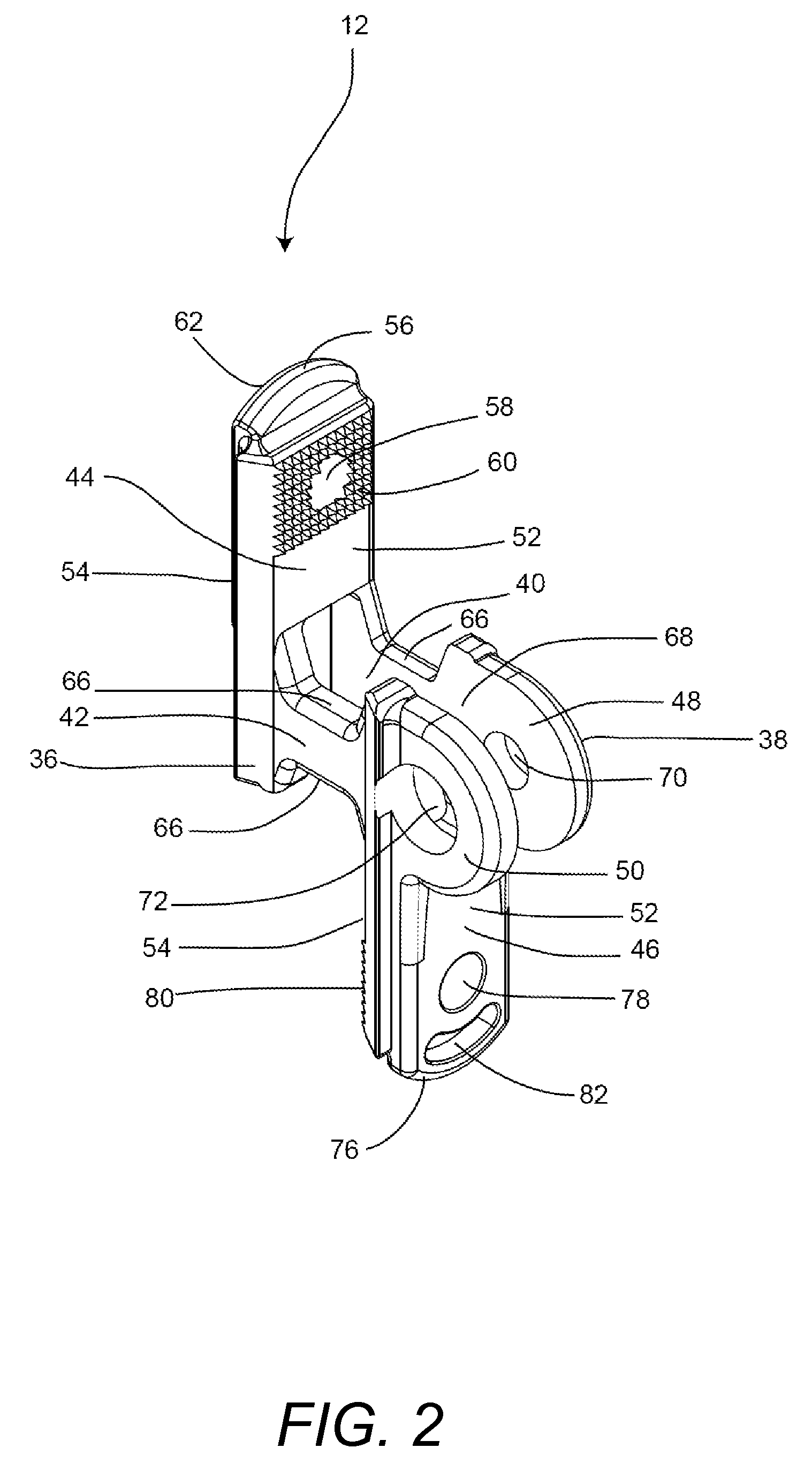
[0029]FIGS. 2 through 8 display the device 10 in more detail. As seen in FIG. 2, the body 12 has an anterior side 36 and a posterior side 38. It includes a pair of crosspieces 40, 42. At a right angle to one end of the crosspieces 40, 42 is a first plate 44. At the opposite end of the crosspieces 40, 42, a pair of rings 48, 50 extends from the crosspieces. In the embodiment depicted in FIGS. 1 and 2 the rings are located at one end of th...


PUM


Abstract

An implantable spinous process stabilization assembly includes a body, a bent arm and a straight arm. The body includes first and second crosspieces arranged parallel to each other, a first plate extending in a direction at right angle to first ends of the first and second crosspieces, first and second rings extending from second ends of the first and second crosspieces, respectively and a second plate extending from a base of the first and second rings, at right angle to the first and second crosspieces and in an opposite direction to the first plate's direction. The bent arm and the straight arm are configured to pivot around an axis perpendicular to the first and second rings and to set first and second pivot angles with the first and second plates, respectively, thereby defining first and second spaces configured to receive and lock onto first and second spinous processes, respectively.

Description

CROSS REFERENCE TO RELATED CO-PENDING APPLICATIONS[0001]This application claims the benefit of U.S. provisional application Ser. No. 60 / 784,557 filed Mar. 21, 2006 and entitled “SPINOUS PROCESS FIXATION DEVICE”, the contents of which are expressly incorporated herein by reference.[0002]This application is also a continuation in part of U.S. application Ser. No. 11 / 609,418 filed on Dec. 12, 2006 and entitled SPINOUS PROCESS FIXATION IMPLANT, the contents of which are expressly incorporated herein by reference.FIELD OF THE INVENTION[0003]The present invention relates to a system and a method for spinal stabilization through an implant, and more particularly to spinal stabilization through attachment of the implant to the spinous processes along one or more vertebras.BACKGROUND OF THE INVENTION[0004]The human spine comprises individual vertebras 330 (segments) that are connected to each other to form a spinal column 329, shown in FIG. 12A. Referring to FIGS. 12B and 12C, each vertebra ...

Claims


Application Information

Patent Timeline
Patent Type & Authority Patents(United States)
IPC IPC(8): A61B17/70
CPCA61B17/7065A61B17/7068
Inventor CHIN, KINGSLEY RICHARDBAKER, DANIEL R.JUSTIN, DANIEL F.
Owner KIC VENTURES LLC
Why Eureka
Try Eureka