Surgical implant

a surgical and implant technology, applied in bone implants, prostheses, medical science, etc., can solve the problems of declining the use of spinal cages and no solid fusion, and achieve the effect of increasing the percentage of successful fusions, high compression strength, and accelerating the process of bony fusion

Inactive Publication Date: 2007-08-09
INION
View PDF10 Cites 28 Cited by
  • Summary
  • Abstract
  • Description
  • Claims
  • Application Information

AI Technical Summary

Benefits of technology

[0009]The cage possesses design features or, alternatively, material features, which allow it to reduce its height permanently within limits when defined load acting along the axis of the spine is exceeded. The cage would then give in to the force until the bone graft inside the cage receives part of the load. The cage stops giving in to the external load as soon as the graft is compacted enough so that it can take over some of the load. The cage follows the so-called subsidence (settling) of the graft. An advantage of the cage of the invention is that it may accelerate the process of bony fusion as the graft material is compressed within the cage and, therefore, it may increase the percentage of su

Problems solved by technology

In a percentage of patients, no solid fusion is obtained, which in some cases is attributed to the fact that cages are too rigid con

Method used


Image

  • Surgical implant
  • Surgical implant
  • Surgical implant

Examples


Embodiment Construction

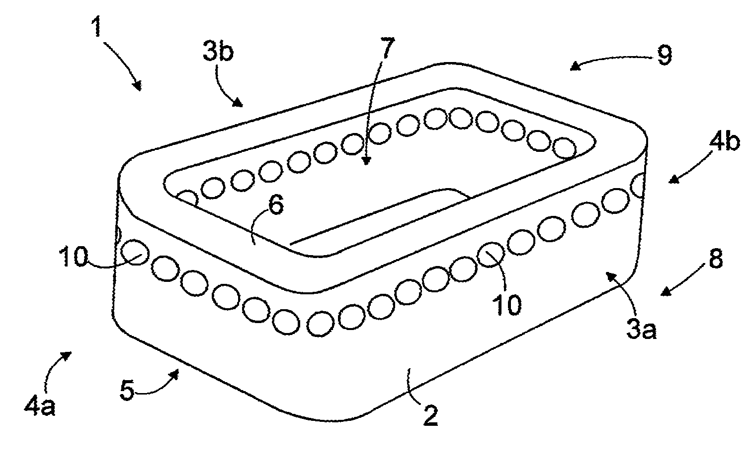
[0027]FIG. 1 is a schematic perspective view of a spinal cage according to the invention. The cage 1 is intended to be inserted between adjacent vertebrae. The cage 1 is particularly useful in an anterior approach for spinal fusion. Nevertheless, other surgical approaches may be utilized including posterior, anterior-lateral, posterior-lateral, etc. Cage 1 could be used in all segments of the spine, i.e. cervical, thoracic and lumbar.

[0028]The cage 1 has a body 2 that can be manufactured from a resorbable material, such as resorbable polymer, copolymer, or polymer mixtures. Examples of suitable polymers are polymers based on polylactide (PLA), polyglycolide (PGA), and trimethylenecarbonate (TMC). As used herein, the term ‘resorbable material’ means that the material is biodegradable, bioerodible, and / or bioabsorbable.

[0029]The body 2 can also be manufactured from a bio-stabile polymer, copolymer or polymer mixtures, or from metal or metal alloy. The term ‘bio-stabile material’ means...


PUM

PropertyMeasurementUnit
Forceaaaaaaaaaa
Heightaaaaaaaaaa
Timeaaaaaaaaaa

Abstract

An implant to be inserted in the disk space between a lower vertebra and an upper vertebra. The implant comprises a body having a lower surface and an upper surface, and an aperture extending through the body in the direction of the height of the body from a lower side of the body to an upper side of the body. The body is arranged to reduce its height permanently under the load the body is exposed to between a lower vertebra and an upper vertebra.

Description

RELATED CASES[0001]This application claims priority from U.S. provisional patent application No. 60 / 772,656, filed Feb. 13, 2006; and from European application number 06101439.5, filed Feb. 9, 2006; both of which are hereby incorporated herein by reference in their entirety for all purposes.FIELD OF THE INVENTION[0002]The invention relates to an implant to be inserted in the disk space between a lower vertebra and an upper vertebra, the implant comprising a body having a lower surface and an upper surface, and an aperture extending through the body in the direction of the height of the body from a lower side of the body to an upper side of the body.BACKGROUND OF THE INVENTION[0003]Spinal cages or interbody fusion devices are frequently used to facilitate bony fusion between two vertebral bodies of the human spine. Interbody fusion of the spine is a surgical treatment procedure which is applied to patients with chronic back pain due to degenerative disk disease (DDD), if it cannot be...

Claims


Application Information

Patent Timeline
IPC IPC(8): A61F2/44
CPCA61F2/4465A61F2310/00155A61F2002/30062A61F2002/30077A61F2002/30133A61F2002/302A61F2002/30598A61F2002/30784A61F2002/3082A61F2002/30841A61F2002/30904A61F2210/0004A61F2210/0066A61F2230/0015A61F2230/0065A61F2310/00017A61F2310/00023A61F2310/00041A61F2310/00095A61F2310/00113A61F2310/00131A61F2002/2835A61F2002/30594
Inventor POSEL, ANDREAS
Owner INION
Why Eureka
Try Eureka