Punch, apparatus and method for forming opposing holes in a hollow part, and a part formed therefrom

a technology of opposing holes and hollow parts, which is applied in the direction of manufacturing tools, transportation and packaging, and other domestic objects, and can solve the problems of slug capture and other problems

Active Publication Date: 2007-08-23
VARI FORM
View PDF11 Cites 9 Cited by
  • Summary
  • Abstract
  • Description
  • Claims
  • Application Information

AI Technical Summary

Problems solved by technology

The presence of a loose slug within the part poses several problems.
Slug capture is also an issue in applications where opposing holes are to be formed in the part.

Method used


Image

  • Punch, apparatus and method for forming opposing holes in a hollow part, and a part formed therefrom
  • Punch, apparatus and method for forming opposing holes in a hollow part, and a part formed therefrom
  • Punch, apparatus and method for forming opposing holes in a hollow part, and a part formed therefrom

Examples


Embodiment Construction

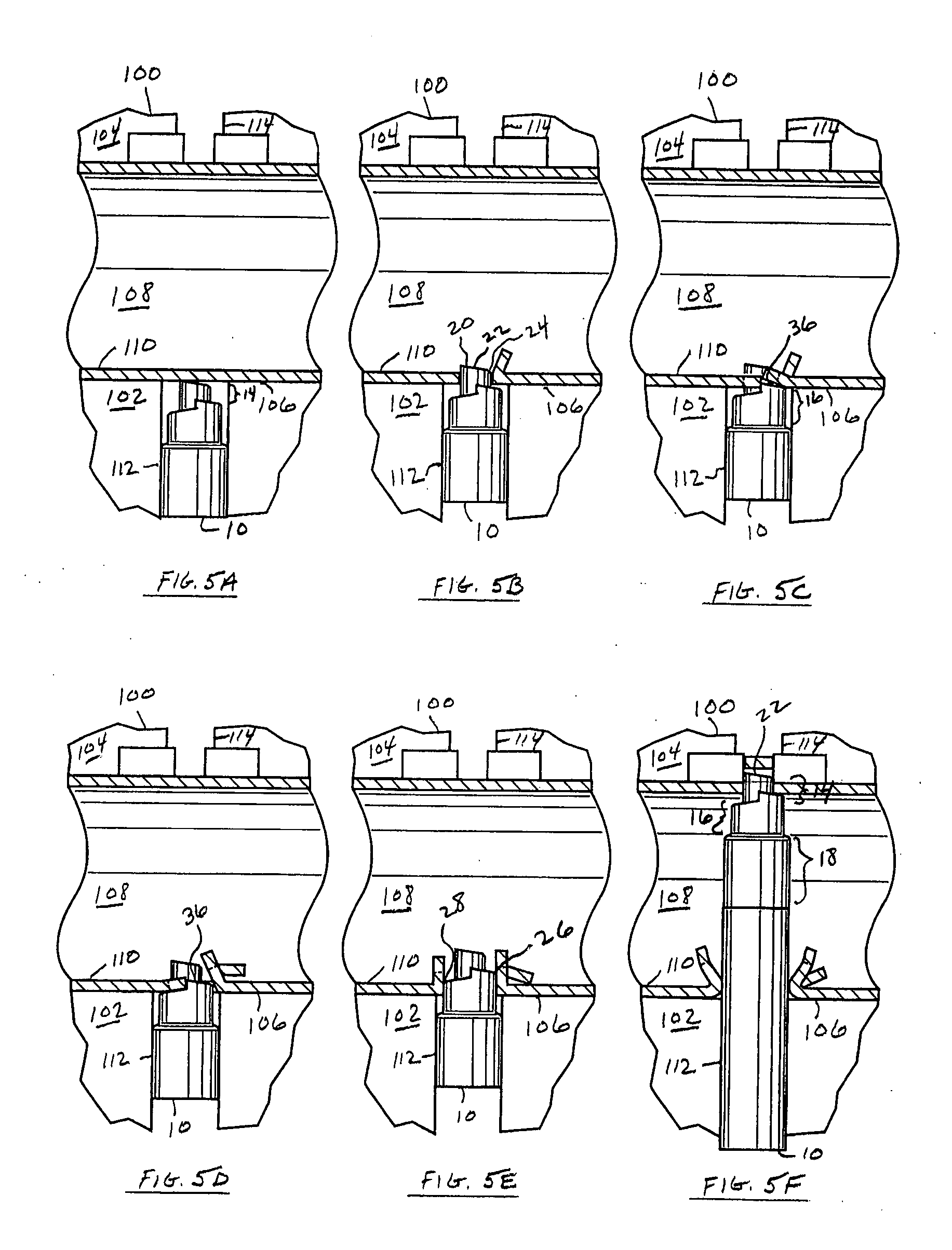
[0022] Referring briefly to FIGS. 5A to 5F, a portion of a hydroforming apparatus 100 suitable for using the present invention will be described. The apparatus 100 comprises a lower die 102 and an upper die 104 that combine to form a die cavity 106 in which a tubular metal part is hydroformed to the die cavity surface. The hydroforming of the tubular metal part is accomplished by the delivery of a suitable hydraulic fluid 108 at a desired pressure to the interior of the tubular metal part resulting in a hydroformed part 110, as shown.

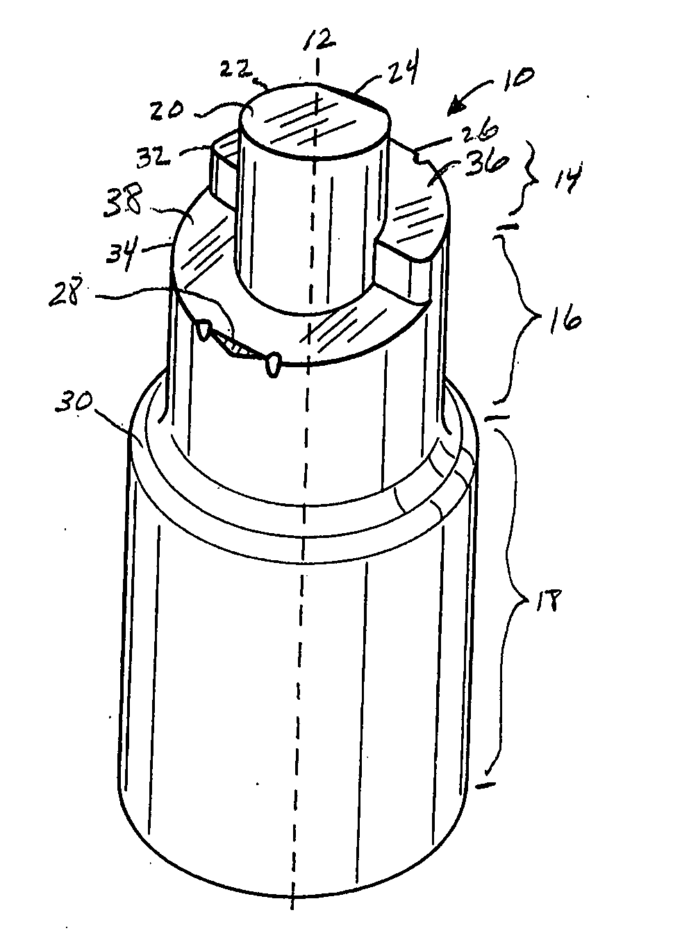
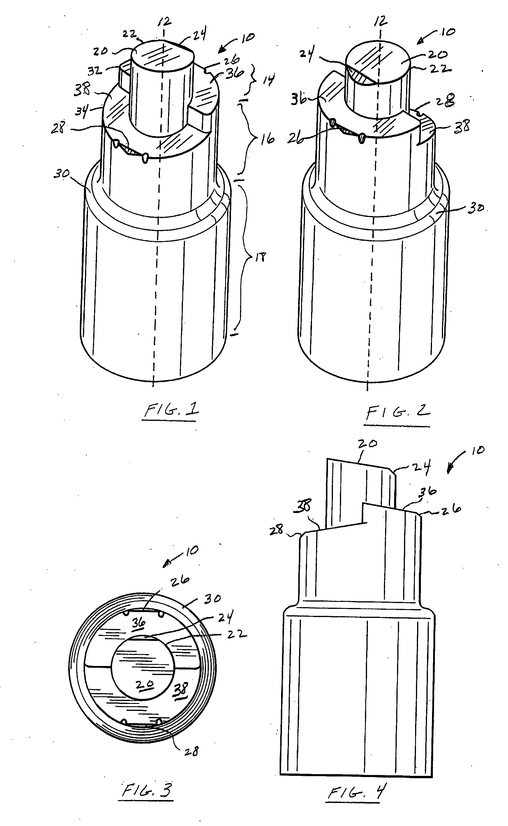
[0023] Reference is now made to FIGS. 1 to 4, which show one embodiment of a punch 10 according to the present invention. The punch 10 is typically used to form opposing holes in a flat wall portion of an internally pressurized part. While the present embodiment is described as applied to a flat wall portion, the punch 10 may also be used on curved wall portions. The punch 10 is particularly adapted for punching opposed entry and exit holes of differin...


PUM

PropertyMeasurementUnit
hole size ratioaaaaaaaaaa
shapeaaaaaaaaaa
pressureaaaaaaaaaa

Abstract

A punch, apparatus and method for forming opposing holes in a hollow part, and a part formed therefrom. The punch includes an end portion adapted to pierce an entry hole and bend material around the entry hole to form a retained slug along an inner edge of the entry hole. The punch also includes an enlarging portion adapted to enter the entry hole after the end portion to enlarge the entry hole by bending the slug and additional material towards the interior′ of the part. The punch has a length greater than a cross-section of the part such that further advancement of the punch through the part punches an exit hole in the part opposite the entry hole.

Description

FIELD OF THE INVENTION [0001] This application relates to a punch, apparatus and method for forming opposing holes in a hollow part, and a part formed therefrom. BACKGROUND OF THE INVENTION [0002] Opposing or aligned holes are sometimes required in hollow parts, such as for connecting mechanical fasteners therethrough. The inside of the part may be pressurized to assist a punch in producing a hole in the part. For example, in the hydroforming of parts from a hollow metal part, the hydroforming pressure is used to assist the punch in producing the hole in the part. This eliminates the need for a secondary operation such as drilling or laser cutting to form the hole in an internally unsupported region of the part. [0003] In a typical punching operation for a hydroformed part, as the punch is advanced to engage the forward surface of the material, the rearward surface is supported by the pressurized fluid. Upon further advancement of the punch through the material to shear a slug, the ...

Claims


Application Information

Patent Timeline
Patent Type & Authority Applications(United States)
IPC IPC(8): B21D28/18
CPCB21D28/28Y10T428/12368Y10T428/1241B21D31/02
Inventor COELHO, JOSE U.DUNN, DAVID J.BLISS, MARTIN L.
Owner VARI FORM
Why Eureka
Try Eureka