
Apparatus and method for dewatering endoscope channels
- Summary
- Abstract
- Description
- Claims
- Application Information
AI Technical Summary
Benefits of technology
Problems solved by technology
Method used
Image

Examples
first embodiment
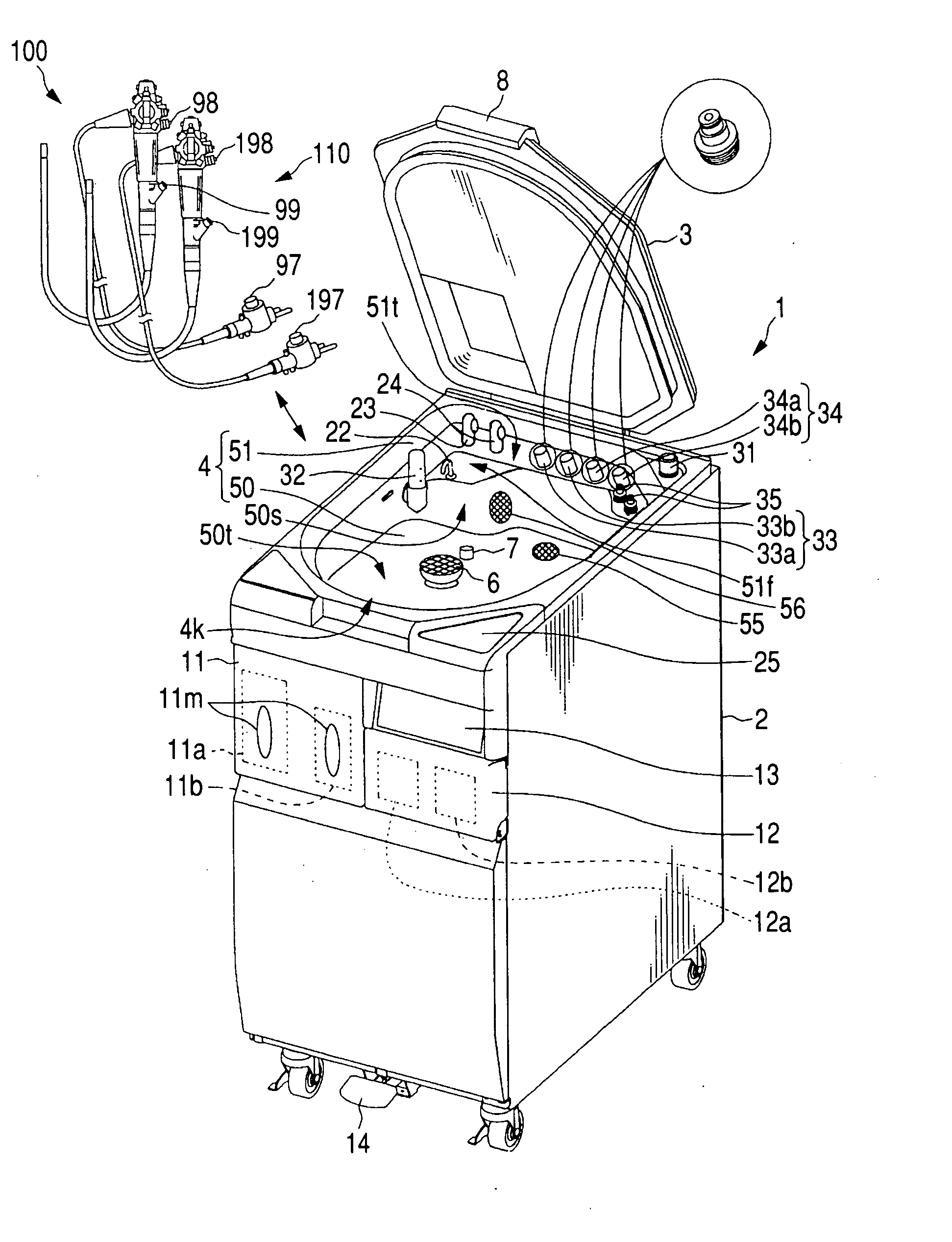
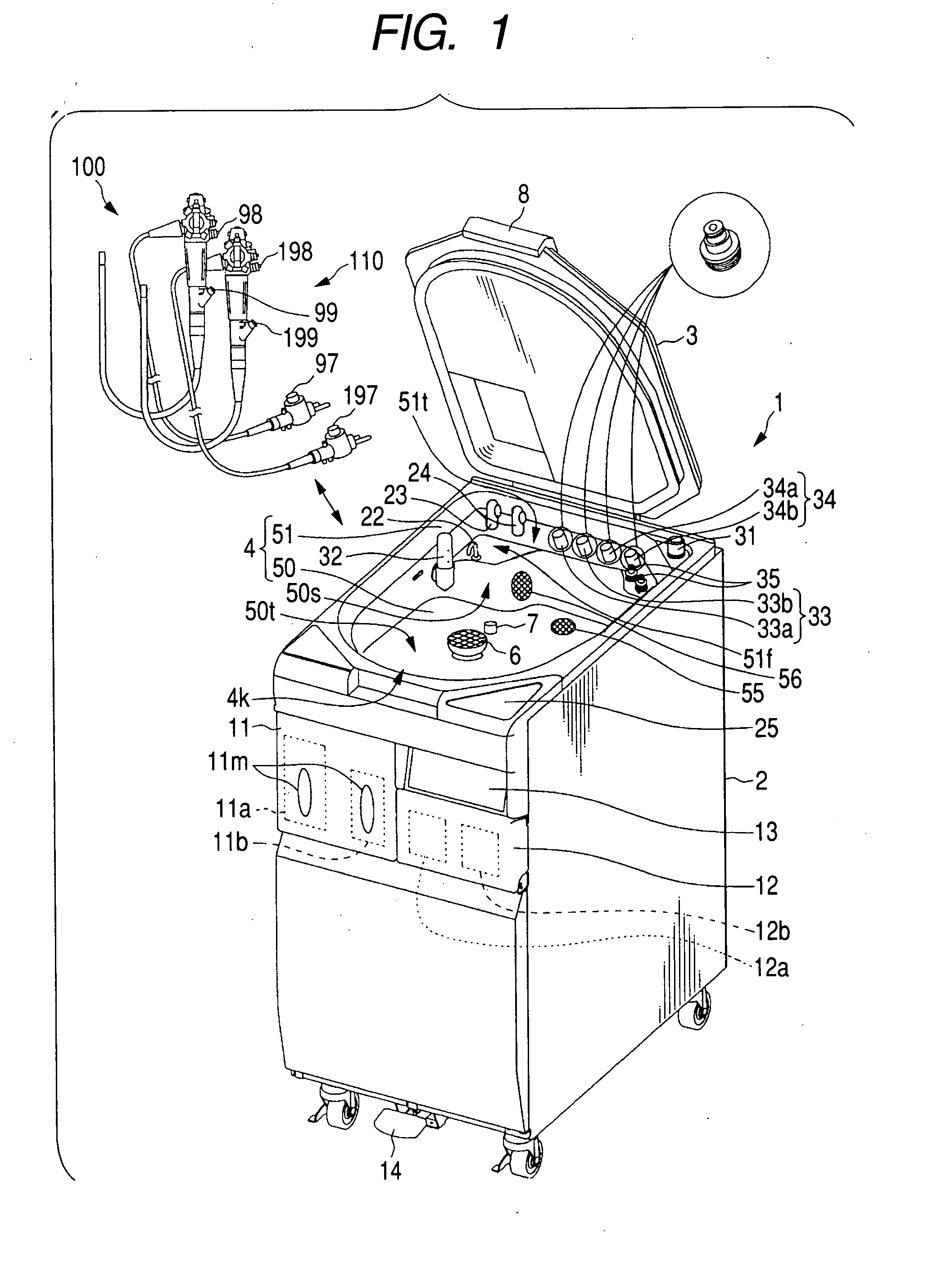
[0051] With reference to FIGS. 1 to 8A and 8B, hereinafter is described a first embodiment of an endoscope washing / disinfecting apparatus embodying a dewatering apparatus and method according to the present invention.
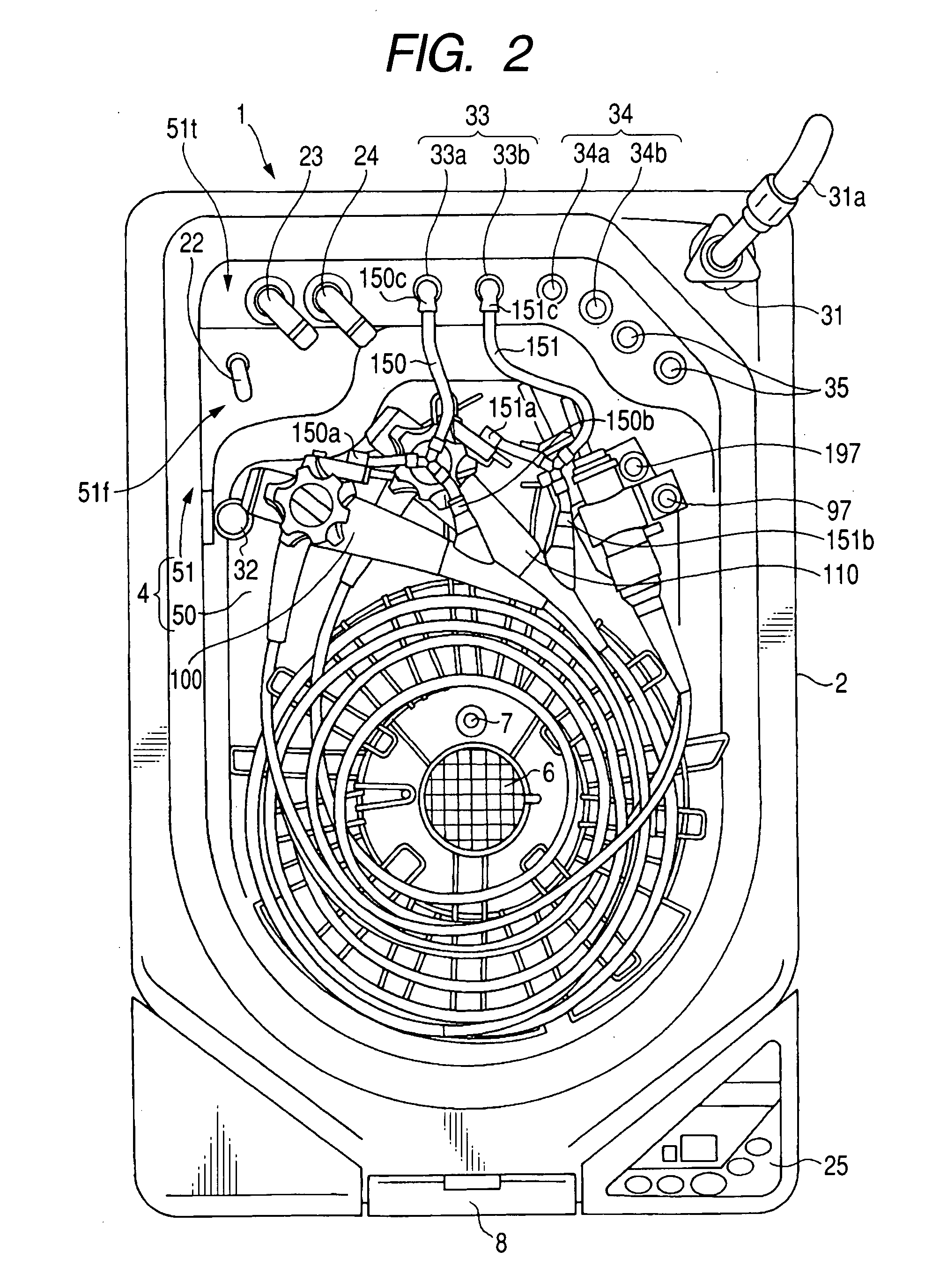
[0052] As shown in FIG. 1, an endoscope washing / disinfecting apparatus 1 is an apparatus for washing / disinfecting two used endoscopes all together (hereinafter, the two endoscopes are referred to as a “first endoscope 100” and a “second endoscope 110”). A principal part of the apparatus is made up of a washing apparatus body (hereinafter referred to just as an “apparatus body”) 2 and a top cover 3 which is connected to a top portion of the apparatus body 2 through a hinge, not shown, for example, so as to be freely opened and closed.
[0053] It will be appreciated that the endoscope washing / disinfecting apparatus 1 may wash / disinfect only one endoscope, i.e. either one of the first endoscope 100 and the second endoscope 110. The present embodiment however will be descri...
second embodiment
[0154] With reference to FIGS. 9 to 14, hereinafter is described an endoscope washing / disinfecting apparatus according to a second embodiment. In the present embodiment and subsequent embodiments, the identical or similar components or processes are given the same references as in the first embodiment for the sake of simplification or omission of explanation.
[0155] The present second embodiment is associated with a washing / disinfecting apparatus which can wash, disinfect and dewater individual types of buttons used in the endoscopes.
[0156]FIG. 9 is an enlarged perspective view of the washing case illustrated in FIG. 1. FIG. 10 illustrates a state where a cover of the washing case illustrated in FIG. 9 has been opened. FIG. 11 is a partial cross-sectional view illustrating a conventional liquid-fluid discharge port of a case channel illustrated in FIG. 4 as well as a washing case. Furthermore, FIG. 12 is a top view illustrating a positional arrangement, in a washing case, of variou...
third embodiment
[0170] With reference to FIGS. 16 to 20, hereinafter is described an endoscope washing / disinfecting apparatus according to a third embodiment. This embodiment is associated with preventing leakage of liquid to the outside of the apparatus.
[0171]FIG. 16 is a perspective view illustrating an inner structure of the apparatus body illustrated in FIG. 1 with no object being accommodated and with its left-side cover member being detached. FIG. 17 is a perspective view illustrating an inner structure of the apparatus body illustrated in FIG. 1 with no object being accommodated and with its right-side cover member being detached.
[0172] Furthermore, FIG. 18 is a partial perspective view illustrating an inner front structure of the apparatus body illustrated in FIG. 1 with no object being accommodated. FIG. 19 is a partial perspective view illustrating an inner rear structure of the apparatus body illustrated in FIG. 1 with no object being accommodated. FIG. 20 is a partial perspective view...
PUM
 Abstract
Description
Claims
Application Information