Pipe joint apparatus, pipe joint structure of heat exchanger, and method of assembling pipe to heat exchanger

a technology of pipe joints and heat exchangers, which is applied in the direction of hose connections, indirect heat exchangers, lighting and heating apparatus, etc., can solve the problems of deteriorating the interim storage capacity increasing the processing cost of the connection step in the manufacturing of the heat exchanger, and increasing the processing cost of the connection step

Inactive Publication Date: 2007-09-06
DENSO CORP
View PDF53 Cites 16 Cited by
  • Summary
  • Abstract
  • Description
  • Claims
  • Application Information

AI Technical Summary

Benefits of technology

[0011] In view of the foregoing problems, it is an object of the present invention to provide a pipe joint apparatus, a heat-exchanger pipe joint structure and a method of assembling a pipe to a heat exchanger, which can effectively reduce and prevent above-described problems.

Problems solved by technology

As disclosed in the patent document 1, however, performing the torch brazing in another step disadvantageously leads to an increase in processing cost in a connection step in manufacturing of the heat exchanger.
This results in poor transportability of the heat exchanger to an assembly workplace where the heat exchanger is to be assembled to an air conditioning duct, and in deteriorated interim storage capability of the heat exchanger at the assembly workplace.
Furthermore, an adjustment step of adjusting an attachment pitch between the pipes needs to be provided, which disadvantageously results in poor productivity.

Method used


Image

  • Pipe joint apparatus, pipe joint structure of heat exchanger, and method of assembling pipe to heat exchanger
  • Pipe joint apparatus, pipe joint structure of heat exchanger, and method of assembling pipe to heat exchanger
  • Pipe joint apparatus, pipe joint structure of heat exchanger, and method of assembling pipe to heat exchanger

Examples


first embodiment

[0031] A first embodiment of the present invention will be now described with reference to FIGS. 1 to 5D.

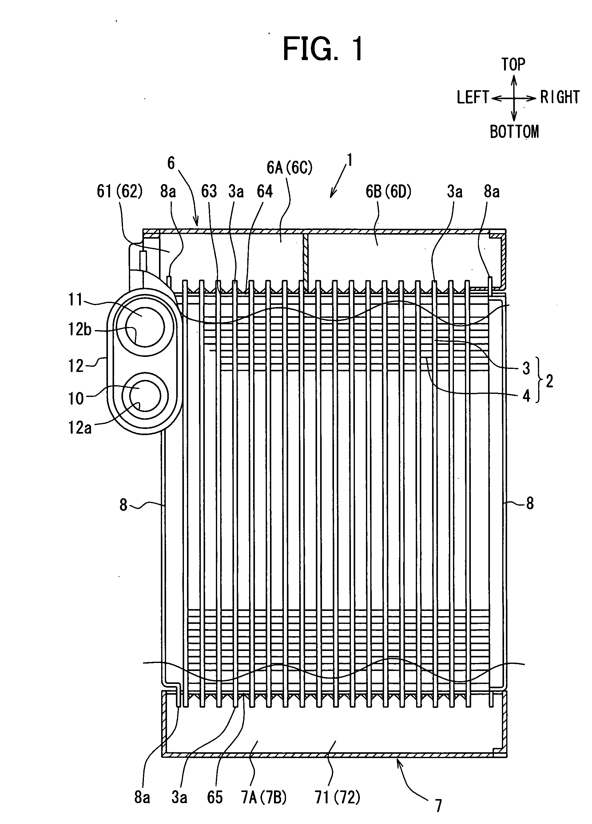
[0032]FIG. 1 is a partial sectional view showing a schematic structure of an evaporator 1 according to the first embodiment. As shown in FIG. 1, an evaporator 1 which is an example of a heat exchanger is constructed of a core portion 2 including tubes 3 and fins 4 which are alternately laminated, an upper tank 6 and a lower tank 7 disposed on upper and lower ends of the core portion 2, and side plates 8 supporting the fins 4 at both ends of the core portion 2. An inlet side refrigerant flow path 10 is connected to an inlet portion 61 of the upper tank 6, while being adjacent to one side plate 8. An outlet side refrigerant flow path 11 is connected to an outlet portion 62. A socket 12 is connected to connect ends of these refrigerant flow paths 10, 11.

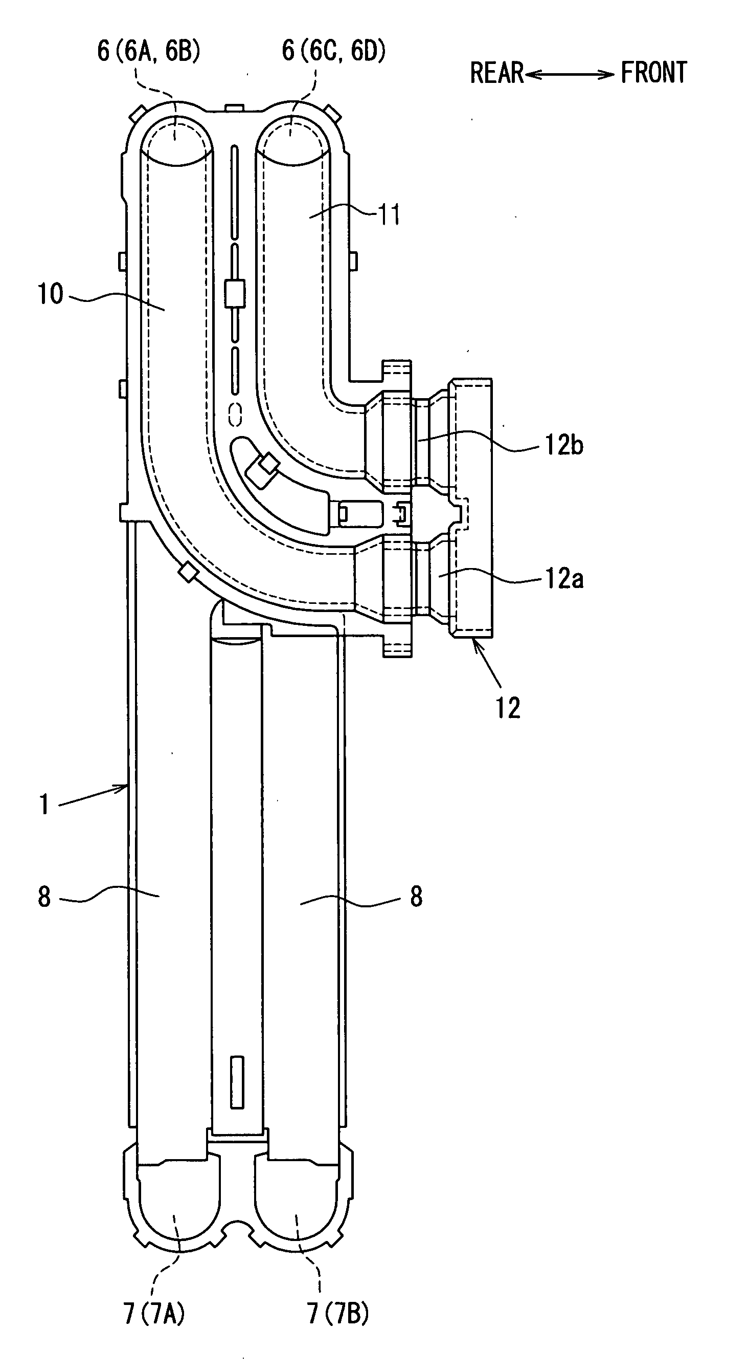
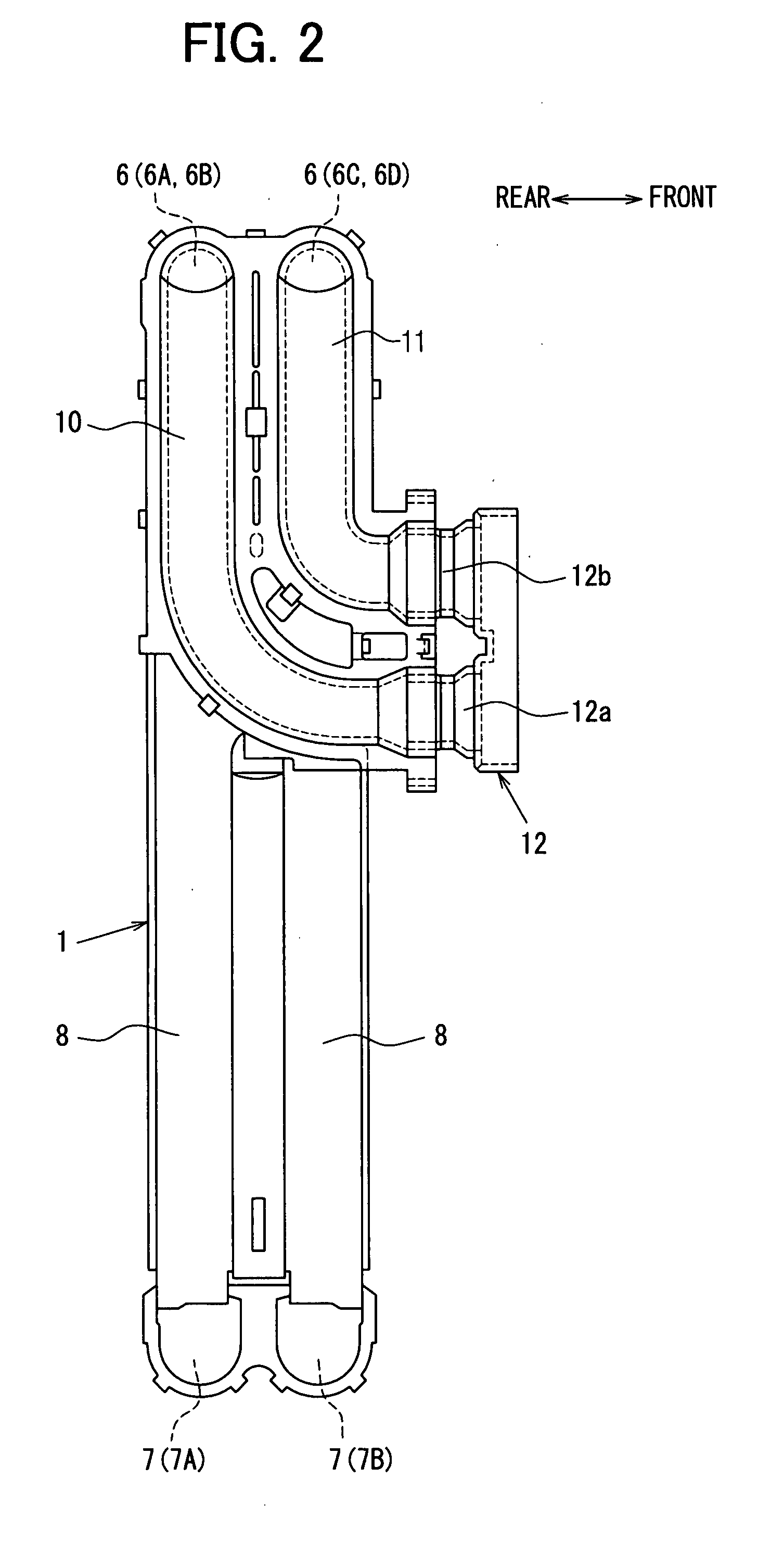
[0033] The evaporator 1 is constructed of an arrangement of two lines in a front and rear direction (seeFIG. 2), each line consis...

second embodiment

[0080] A second embodiment of the present invention will be now described with reference to FIGS. 6A to 6C.

[0081] In the second embodiment, in order to improve the corrosion protection property of the seal surfaces of the O-rings 16, 17, a sacrificial corrosive material 13c is formed to be positioned in the vicinity of the seal surfaces of the O-rings 16, 17. That is, by providing the sacrificial corrosive material 13c in the vicinity of the connection plate 13, the corrosion protection property of the seal surfaces of the O-rings 16, 17 is improved, at a position on which the outer peripheral edges of the O-rings 16, 17 abut against the inner peripheral edges of the second inner circumferential portions 123a, 123b formed in the socket 12.

[0082] First, as shown in FIG. 6A, the sacrificial corrosive material 13c is integrally formed with the connection plate 13 at one end surface side at which the O-rings 16, 17 of the connection plate 13 are disposed. In other words, the connectio...

third embodiment

[0088] A third embodiment of the present invention will be now described with reference to FIGS. 7A to 8.

[0089] Although in the above-described embodiments, the plurality of drain holes 128 are formed in the root (lower end part) of the connection portion 121 of the socket 12 so as to discharge the condensed water entering the socket 12, drain holes 138a to 138f may be formed in the connection plate 13. In this case, as shown in FIGS. 7A to 7F, the drain holes 138a to 138f can be formed at different positions.

[0090] When the socket 12 and the connection plate 13 are disposed vertically or in the up-down direction (top-bottom direction in FIG. 7A) such that the inlet pipe 14 and the outlet pipe 15 are arranged in the upper-down direction, that is, in the direction of gravity, as shown in FIG. 7A, the drain holes 138a, 138b may be formed on the upper and lower ends of the connection plate 13. That is, the drain holes 138a, 138b may be provided at least on the uppermost and lowermost...


PUM

PropertyMeasurementUnit
radial dimensionaaaaaaaaaa
corrosiveaaaaaaaaaa
gravityaaaaaaaaaa

Abstract

A pipe joint structure includes a plurality of fluid flow path portions, a socket connected to the fluid flow path portions, a connection plate disposed to abut against the socket, a plurality of pipes connected to each other by the connection plate, and a seal member disposed between the plurality of pipes and the socket. The socket includes a connection portion that is located to cover an edge of the connection plate and to fix the plurality of pipes to the plurality of fluid flow path portions. The pipe joint structure can be suitably used for a heat exchanger.

Description

CROSS REFERENCE TO RELATED APPLICATION [0001] This application is based on Japanese Patent Applications No. 2006-41420 filed on Feb. 17, 2006, and No. 2007-3926 filed on Jan. 11, 2007, the contents of which are incorporated herein by reference in its entirety. FIELD OF THE INVENTION [0002] The present invention relates to a pipe joint apparatus for connecting a plurality of fluid flow path portions with a plurality of pipes, to a heat-exchanger pipe joint structure using the same, and to a method of assembling pipes to a heat exchanger, which are suitable for use in, for example, a refrigerant pipe joint of a refrigeration cycle for air conditioning. BACKGROUND OF THE INVENTION [0003] Such pipe joint structures for heat exchangers have hitherto been known in, for example, a patent document 1. Specifically, in a heat exchanger, fins are provided between a plurality of tubes through which refrigerant flows to form a core portion, and a pair of tank portions are disposed on both ends o...

Claims


Application Information

Patent Timeline
Patent Type & Authority Applications(United States)
IPC IPC(8): F16L35/00B21D53/00
CPCF16L13/122F16L21/035F16L39/00F16L41/001F28F9/0248Y10T29/49373F28F19/00F28D1/05391F28D2021/0071F28F2230/00F28F9/0256
Inventor KATOH, YOSHIKINAKAMURA, MITSUGUSHIMIZU, ARINORIKAMIYA, SADAYUKINAGANAWA, HIROKINAGOYA, TAKAHARUHIROSE, TAKAYUKI
Owner DENSO CORP
Why Eureka
Try Eureka