Needle holder for a sewing machine

a technology for sewing machines and needle holders, which is applied in the direction of needle bars, sewing machines, textiles and paper, etc., can solve the problems of easy adjustment of stitching plates even by less skilled operators, and achieve the effect of avoiding collisions between the adjustment device and other elements of the sewing machine, avoiding erroneous adjustments, and optimal gripper distan

Active Publication Date: 2007-09-27
GROZ BECKERT KG
View PDF10 Cites 5 Cited by
  • Summary
  • Abstract
  • Description
  • Claims
  • Application Information

AI Technical Summary

Benefits of technology

[0019] Referring to a currently preferred embodiment, the adjustment device is an eccentric adjustment device. This device comprises, e.g., two cams which are supported so as to be rotatable about rotary axes extending longitudinally to the needle bar. In addition, the eccentric adjustment device is preferably combined with a linear guide device that pre-specifies a guide direction extending transversely to the needle bar. As a result of the interaction of the eccentric adjustment device and the linear guide device, a slim adjustment device is created, said device having an exterior contour that does not project beyond the exterior contour of the needle holder. Consequently, collisions between the adjustment device and other elements of the sewing machine are largely prevented. It is easily possible to integrate the adjustment device in existing machine designs.
[0020] It is possible to manually perform the adjustment. Appropriate manual adjustment devices preferably are stepped adjustment devices. Thus, erroneous adjustments are easily prevented. The operator only needs to select the correct engagement step or adjustment step. The adjustment may be achieved by means of a selector shaft, an incremental advance, a series connection or even with the use of appropriate shims. Likewise, it is possible to adjust the distance between the sewing needle and the gripper by electronic means, namely, by employing piezo technology, i.e., piezo drives or a servo motor. Electronic enabling or control is particularly advantageous because the desired machine settings can be maintained in a reproducible manner.
[0021] In the ideal case, each needle gauge is assigned to exactly one position of the sewing needle or of the adjustment device, which accomplishes that an optimal gripper distance is maintained. If an electronic control is used, a continuous adjustment option is advantageous.

Problems solved by technology

However, a stitch plate change is easily accomplished even by less skilled operators.

Method used


Image

  • Needle holder for a sewing machine
  • Needle holder for a sewing machine
  • Needle holder for a sewing machine

Examples


Embodiment Construction

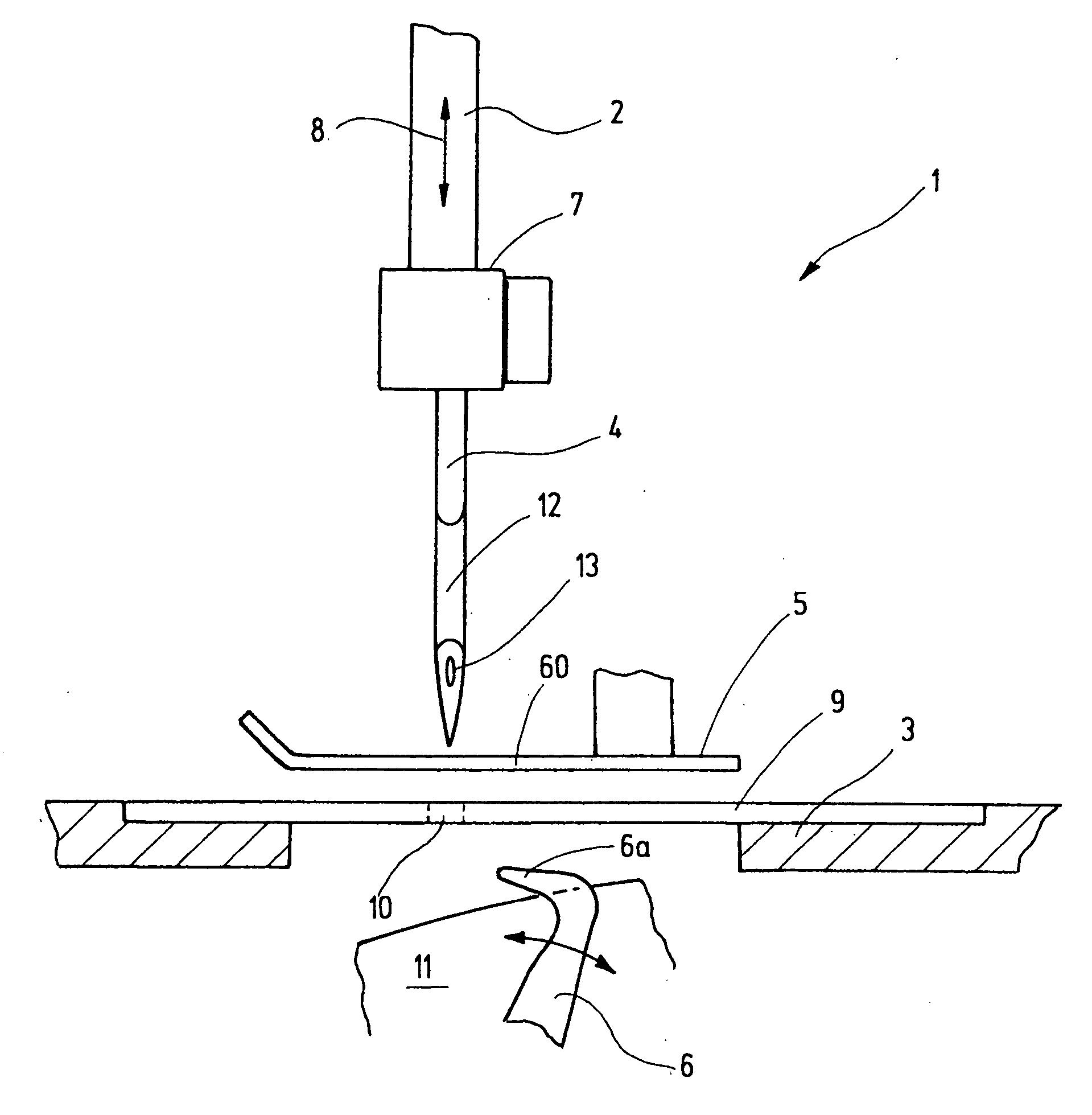
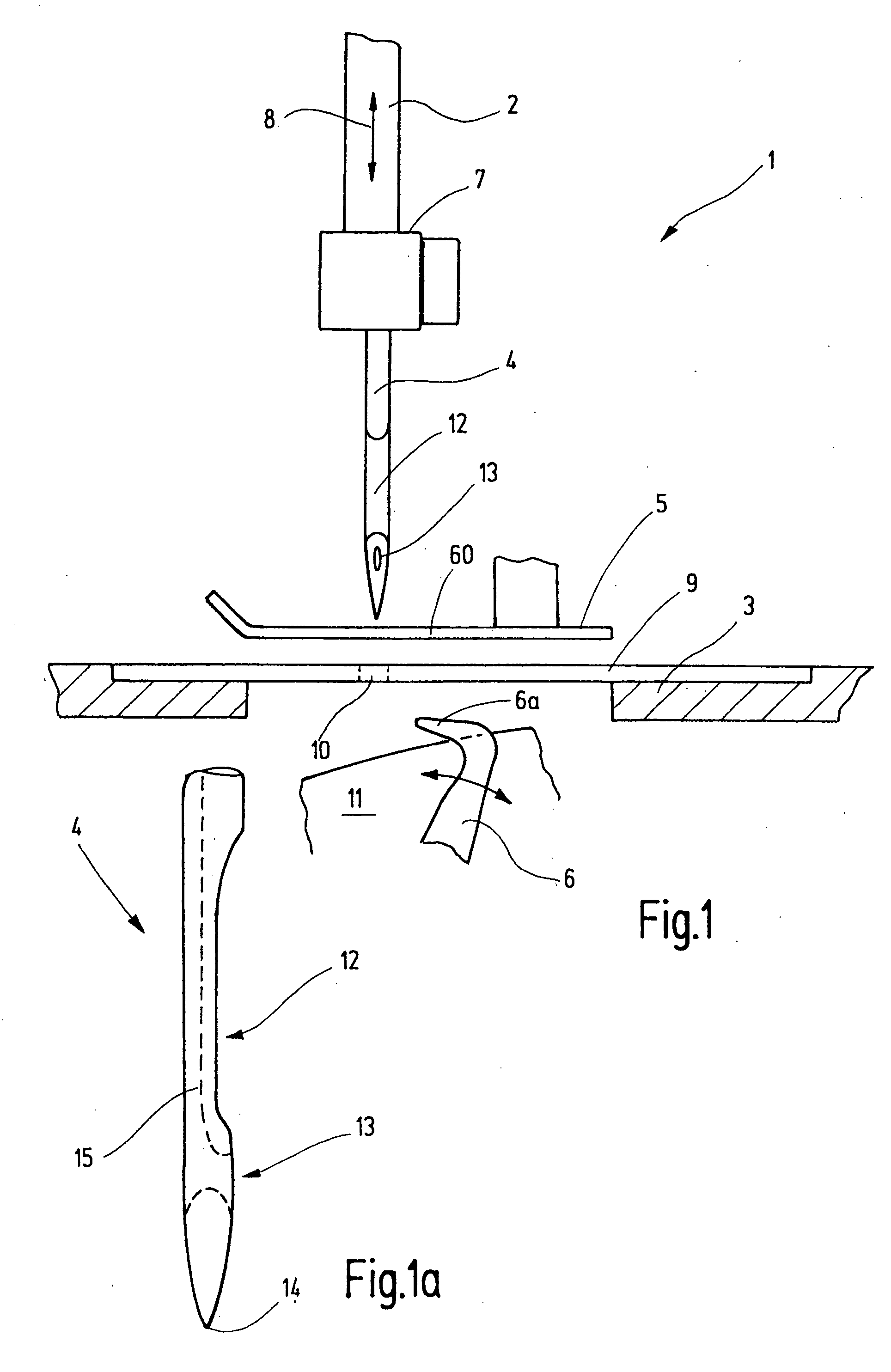
[0040]FIG. 1 is a schematic illustration of a section of a sewing machine 1 comprising a needle bar 2 of a table 3 belonging to the sewing machine 1, a sewing needle 4, a foot 5 and a gripper 6. The illustrated gripper 6 is an alternating gripper 6 having a horizontal axis of rotation. The depiction of an alternating gripper 6 has been chosen as an example; whereby the same also applies to rotating grippers. The sewing needle 4 is attached to the needle bar 2 by means of a needle holder 7. The needle bar 2 is connected to a drive device and can be driven in a back-and-forth moving manner as schematically illustrated by an arrow 8 in FIG. 1. In so doing, it performs a linear motion along the longitudinal direction of the sewing needle 4. In other words, the sewing needle 4 is aligned parallel to the needle bar 2 and its direction of movement. The sewing needle 4 has, on its upper end, a cylindrical section, which is referred to as the shank and is used to attach the sewing needle 4. ...


PUM


Abstract

A needle holder (7) is provided, in particular, for industrial sewing machines, in which sewing machine needles having different needle gauges and preferably different cylindrical shanks or shafts are supported or held in such a manner that they can be adjusted in a transverse direction. This permits an adjustment of the relative position between the sewing needle (4) and the gripper (6), without requiring an adjustment of the gripper position and/or the needle guard position.

Description

CROSS REFERENCE TO RELATED APPLICATION [0001] This application claims the priority of European Patent No. 06 005 802.1, filed on Mar. 22, 2006, the subject matter of which, in its entirety, is incorporated herein by reference. BACKGROUND OF THE INVENTION [0002] The invention relates to a needle holder for a sewing machine, in particular an industrial sewing machine. Referring to sewing machines, the needle holder, the stitch plate, the gripper and the needle guard must be positioned precisely relative to each other, in order to ensure reliable stitching, especially when sewing occurs at a high sewing speed and with a high number of stitches. If the adjustment of the position of the gripper relative to the needle is inadequate, faulty stitching, needle and thread breakage, as well as damage to the gripper and the needle guard may occur. [0003] Referring in particular to the thickness of sewing needles, they are selected in view of the material that is to be sewn. Accordingly, there i...

Claims


Application Information

Patent Timeline
Patent Type & Authority Applications(United States)
IPC IPC(8): D05B55/02
CPCD05B55/14D05B55/00D05B55/02
Inventor HILLENBRAND, BERNDBINDER, BERND
Owner GROZ BECKERT KG
Why Eureka
Try Eureka