Terminal and transmission method for transmitting repetition signals using a transmission format that accommodates SRS transmission

a transmission format and repeater technology, applied in the field of terminals and transmission methods, can solve problems such as undesirable complexity of the demodulation process in the base station, collapse of the orthogonality between the occ sequence, and the inability to adapt to the transmission format of the repeater signal, so as to prevent the collision between the data signal of the mtc coverage enhancement terminal and the srs. the effect of reducing the effect of an existing lte system

Active Publication Date: 2019-10-22
PANASONIC INTELLECTUAL PROPERTY CORP OF AMERICA
View PDF1 Cites 0 Cited by
  • Summary
  • Abstract
  • Description
  • Claims
  • Application Information

AI Technical Summary

Benefits of technology

[0019]In a cell that supports MTC terminals, the MTC terminals and existing LTE terminals need to coexist, and the MTC terminals are desirably supported in such a way as to minimize an effect upon an existing LTE system. In uplink transmission (e.g., PUSCH transmission) of an MTC terminal (MTC coverage enhancement terminal) that requires repetition transmission, therefore, data transmission is not performed with SRS resource candidates in order to prevent a collision with SRSs of the existing LTE system. As a result, a collision between an SRS and a data signal of the MTC coverage enhancement terminal is prevented.
[0021]One is a method in which, as illustrated in FIG. 1, data is mapped in 12 SC-FDMA symbols other than a DMRS and a last SC-FDMA symbol, which is an SRS resource candidate, is punctured (e.g., refer to R1-151587, Samsung, “Considerations of legacy SRS impact on uplink transmission from low-cost UE,” April 2015). Because the SRS transmission candidate subframes and the other subframes transmit the same signals in symbols other than the last SC-FDMA symbol in this method, coherent combining can be easily achieved on a base station side.
[0026]One non-limiting and exemplary embodiment provides a base station, a terminal, a reception method, and a transmission method capable of improving channel estimation accuracy through cross-subframe channel estimation and symbol level combining even if SRS transmission candidate subframes are included.
[0028]According to an aspect of the present disclosure, the channel estimation accuracy can be improved through the cross-subframe channel estimation and the symbol level combining even if SRS transmission candidate subframes are included.

Problems solved by technology

Because a part of OCCs is punctured in this method, however, orthogonality between OCC sequences collapses, and characteristics might deteriorate due to interference between codes.
Because ACK / NACK signals are multiplied by different OCC sequences between the SRS transmission candidate subframes and the other subframes in this method, however, signals before de-spreading are not subjected to coherent combining on the base station side, and a demodulation process in the base station undesirably becomes complicated.

Method used


Image

  • Terminal and transmission method for transmitting repetition signals using a transmission format that accommodates SRS transmission
  • Terminal and transmission method for transmitting repetition signals using a transmission format that accommodates SRS transmission
  • Terminal and transmission method for transmitting repetition signals using a transmission format that accommodates SRS transmission

Examples


first embodiment

Configuration of Base Station

[0055]FIG. 9 is a block diagram illustrating the configuration of the base station 100 according to a first embodiment of the present disclosure. In FIG. 9, the base station 100 includes the control unit 101, a control signal generation unit 102, a control signal encoding unit 103, a control signal modulation unit 104, a data encoding unit 105, a retransmission control unit 106, a data modulation unit 107, a signal assignment unit 108, an IFFT (Inverse Fast Fourier Transform) unit 109, a CP addition unit 110, a transmission unit 111, an antenna 112, the reception unit 113, a CP removal unit 114, a PUCCH extraction unit 115, a combining unit 116, a demapping unit 117, a channel estimation unit 118, an equalization unit 119, a de-spreading unit 120, a correlation processing unit 121, and a determination unit 122.

[0056]The control unit 101 determines an SRS resource candidate group in a cell covered by the base station 100 in consideration of the number of ...

second embodiment

[0122]In an existing LTE system, a PUCCH is located at both edges of a system band along a frequency domain, and frequency hopping (inter-slot frequency hopping) is performed between the first and second slots.

[0123]In MTC, whose specifications are being examined in LTE-Advanced Release 13, on the other hand, an MTC terminal supports only a frequency bandwidth of 1.4 MHz (narrow band) in order to reduce the cost of the terminal (MTC terminal).

[0124]In MTC, therefore, it is considered that contribution to communication characteristics is larger in producing an effect of improving the estimation accuracy of channel estimation using reference signals in two slots of each subframe than in producing a frequency diversity effect through inter-slot frequency hopping within the 1.4 MHz band.

[0125]In the present embodiment, therefore, a case will be described in which, in PUCCH repetition, a PUCCH is transmitted using the same resources (that is, the same format) between the first and second...

third embodiment

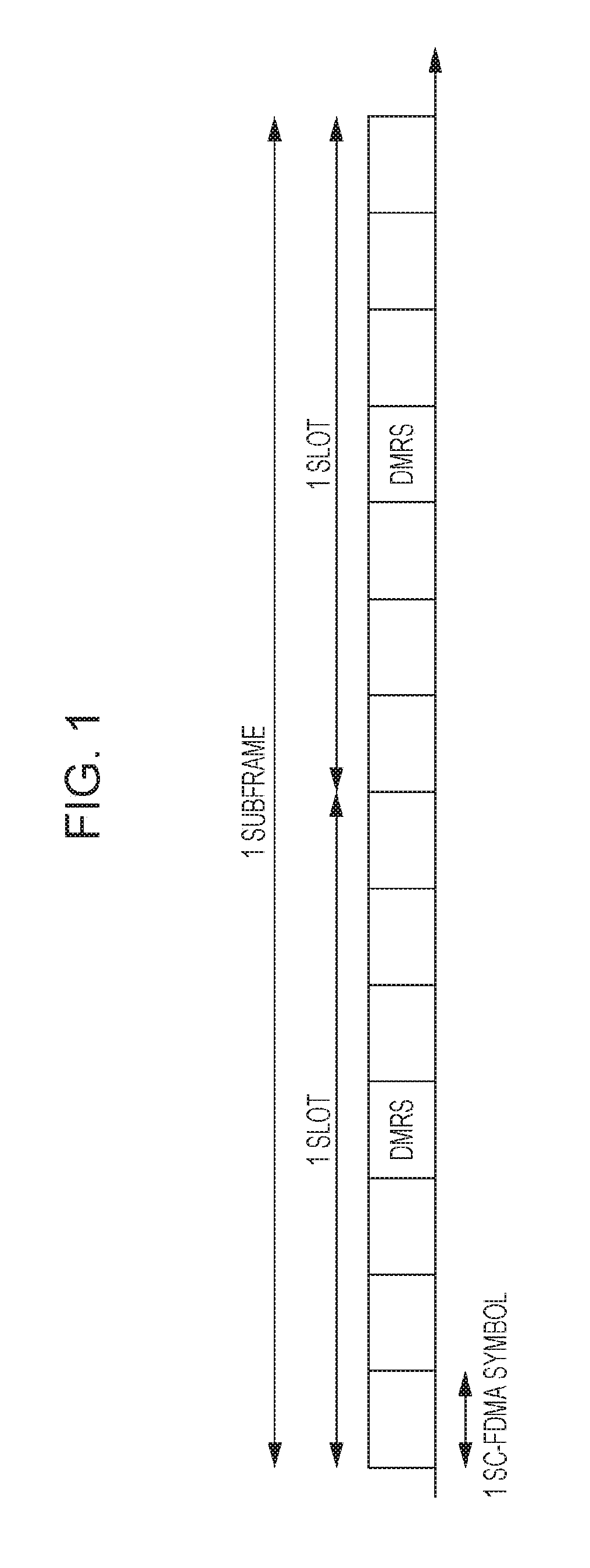
[0143]In the first and second embodiments, if there is even one SRS transmission candidate subframe in the X-subframe period, a response signal is not transmitted using last SC-FDMA symbols (e.g., refer to FIG. 11) or seventh SC-FDMA symbols and the last SC-FDMA symbols (that is, a last SC-FDMA symbol of each slot; e.g., refer to FIG. 12) of all the X subframes, and overhead becomes large.

[0144]In the present embodiment, therefore, a method for minimizing symbols with which a response signal is not transmitted and reducing the overhead will be described.

[0145]A base station and a terminal according to the present embodiment have the same basic configurations as the base station 100 and the terminal 200 according to the first embodiment and will be described with reference to FIGS. 9 and 10.

[0146]The base station 100 transmits srs-SubframeConfig to the terminal 200 through cell-specific higher layer signaling for setting an SRS resource candidate group.

[0147]In addition, before a PUC...


PUM


Abstract

A repeater generates repetition signals by repeating an uplink signal over a plurality of subframes. If the plurality of subframes do not include a transmission candidate subframe of a sounding reference signal used to measure uplink reception quality, a controller sets a first transmission format to all the plurality of subframes, and if the plurality of subframes include the transmission candidate subframe, the controller sets a second transmission format to all the plurality of subframes. A transmitter transmits the repetition signals using the set transmission format.

Description

BACKGROUND1. Technical Field[0001]The present disclosure relates to a base station, a terminal, a reception method, and a transmission method.2. Description of the Related Art[0002]In the 3rd Generation Partnership Project Long Term Evolution (3GPP LTE), orthogonal frequency-division multiple access (OFDMA) is adopted as a communication method for downlink from a base station (also referred to as “Evolved Node B (eNB)”) to a terminal (also referred to as “user equipment (UE)”). Single-carrier frequency-division multiple access (SC-FDMA) is adopted as a communication method for uplink from a terminal to a base station (e.g., refer to 3GPP TS 36.211 V12.5.0, “Evolved Universal Terrestrial Radio Access (E-UTRA); Physical channels and modulation (Release 12),” March 2015, 3GPP TS 36.212 V12.4.0, “Evolved Universal Terrestrial Radio Access (E-UTRA); Multiplexing and channel coding (Release 12),” March 2015, and 3GPP TS 36.213 V12.5.0, “Evolved Universal Terrestrial Radio Access (E-UTRA);...

Claims


Application Information

Patent Timeline
Patent Type & Authority Patents(United States)
IPC IPC(8): H04L5/00H04L27/26H04L1/08H04J13/18H04J13/00H04W4/70H04W72/04
CPCH04J13/18H04W4/70H04L1/08H04L5/0051H04L5/001H04J13/004H04L5/0062H04W72/0406H04L27/2643H04L27/2602H04L5/0048H04L5/0094H04L25/0204H04L25/0224H04L1/1671H04B7/066H04L27/26035H04W72/20
Inventor YAMAMOTO, TETSUYASUZUKI, HIDETOSHIHORIUCHI, AYAKO
Owner PANASONIC INTELLECTUAL PROPERTY CORP OF AMERICA
Why Eureka
Try Eureka