
Cot height indicator

a technology of height indicator and cot, which is applied in the field of ambulance cots, can solve the problems that operators often find it difficult to quickly adjust a cot repeatedly to a specific desired level, and achieve the effect of improving the comfort of patients

Inactive Publication Date: 2007-10-25
FERNO WASHINGTON
View PDF8 Cites 19 Cited by
  • Summary
  • Abstract
  • Description
  • Claims
  • Application Information

AI Technical Summary

Benefits of technology

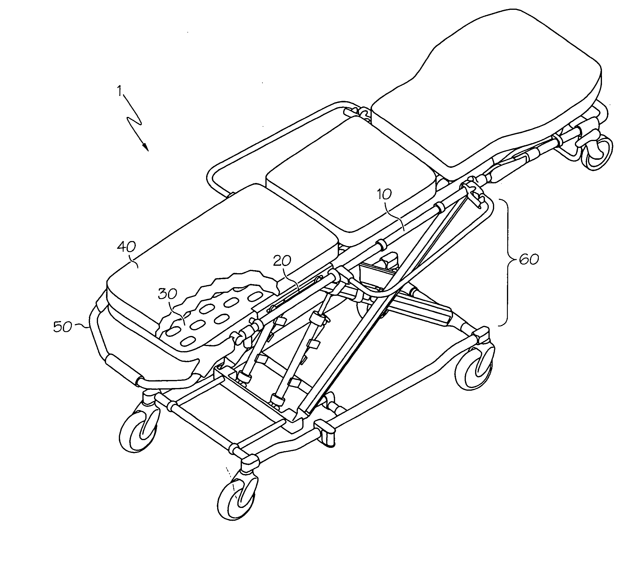
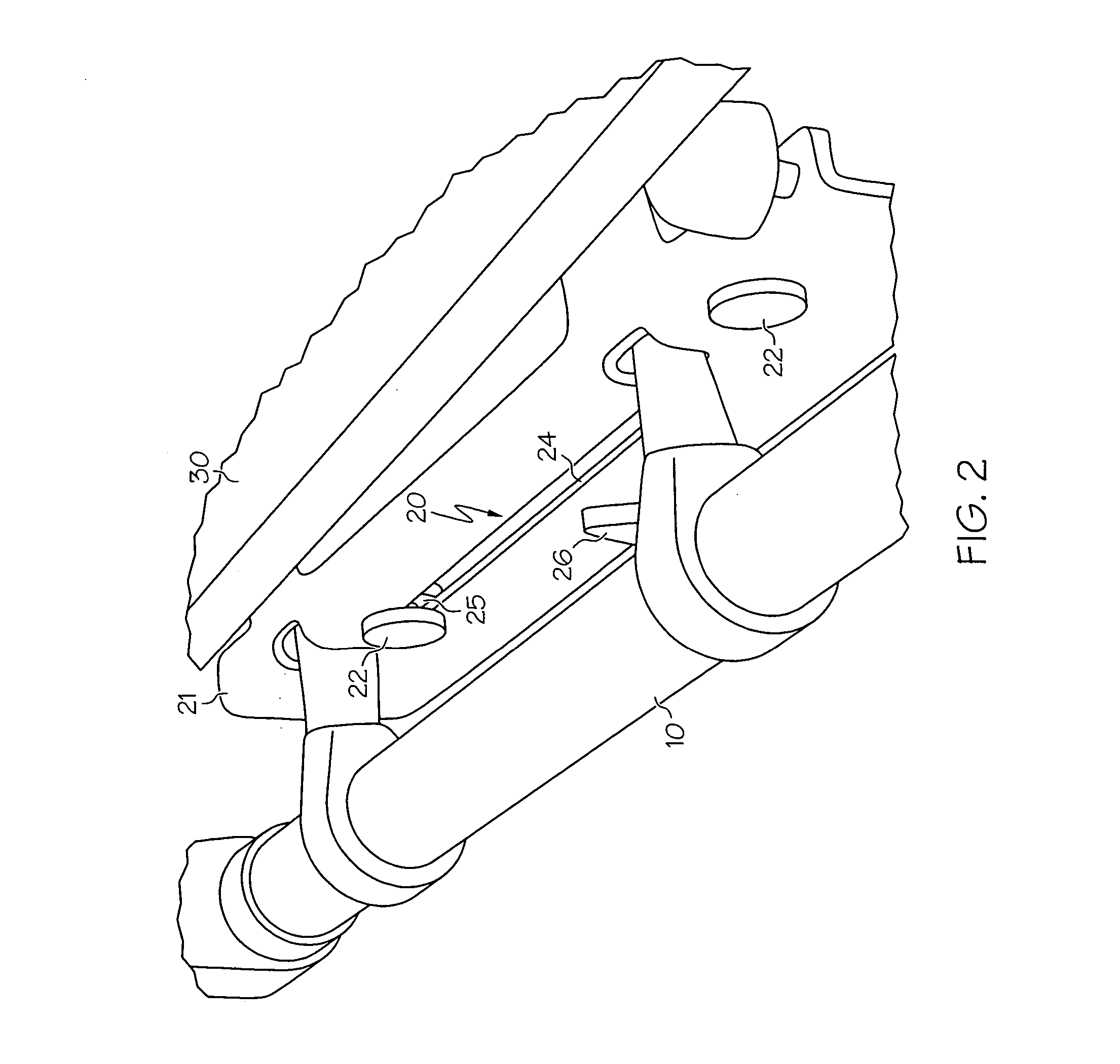
[0003] In a first embodiment of the present invention, a patient transport cot is provided. The patient transport cot comprises a height adjustment component coupled to the patient transport cot and configured to raise or lower the cot to a plurality of heights. The patient transport cot further comprises a mechanical height indicator coupled to the patient transport cot and comprising at least one height setting, wherein each height setting corresponds to a target cot height. The mechanical height indicator further comprises a moving height marker configured to move with the cot as the cot is raised or lowered, wherein the cot is adjusted to the target cot height when the moving height marker is aligned with the height setting.
[0004] In a second embodiment of the present invention, a patient transport cot is provided. The patient transport cot comprises a height adjustment component coupled to the patient transport cot and configured to raise or lower the cot to a plurality of heights. The patient transport cot further comprises an electronic height indicator coupled to the patient transport cot and comprising at least one height sensor, wherein each height sensor represents a target cot height. The electronic height indicator further comprises at least one visual display component coupled to the sensor, wherein the height sensor is triggered when the cot is adjusted to the target cot height setting represented by the height sensor. The triggering of the height sensor actuates the visual display component.
[0005] In a third embodiment of the present invention, a method is provided for adjusting the height of a patient transport cot to a target height. The method comprises providing a patient transport cot, w

Problems solved by technology

However, this flexibility also creates problems, especially with cots having infinite adjustments within a height range.
Operators often find it difficult to quickly adjust a cot repeatedly to a specific desired level, for example, a load height for an emergency vehicle or even a hospital bed.

Method used


Image

  • Cot height indicator
  • Cot height indicator
  • Cot height indicator

Examples


Embodiment Construction

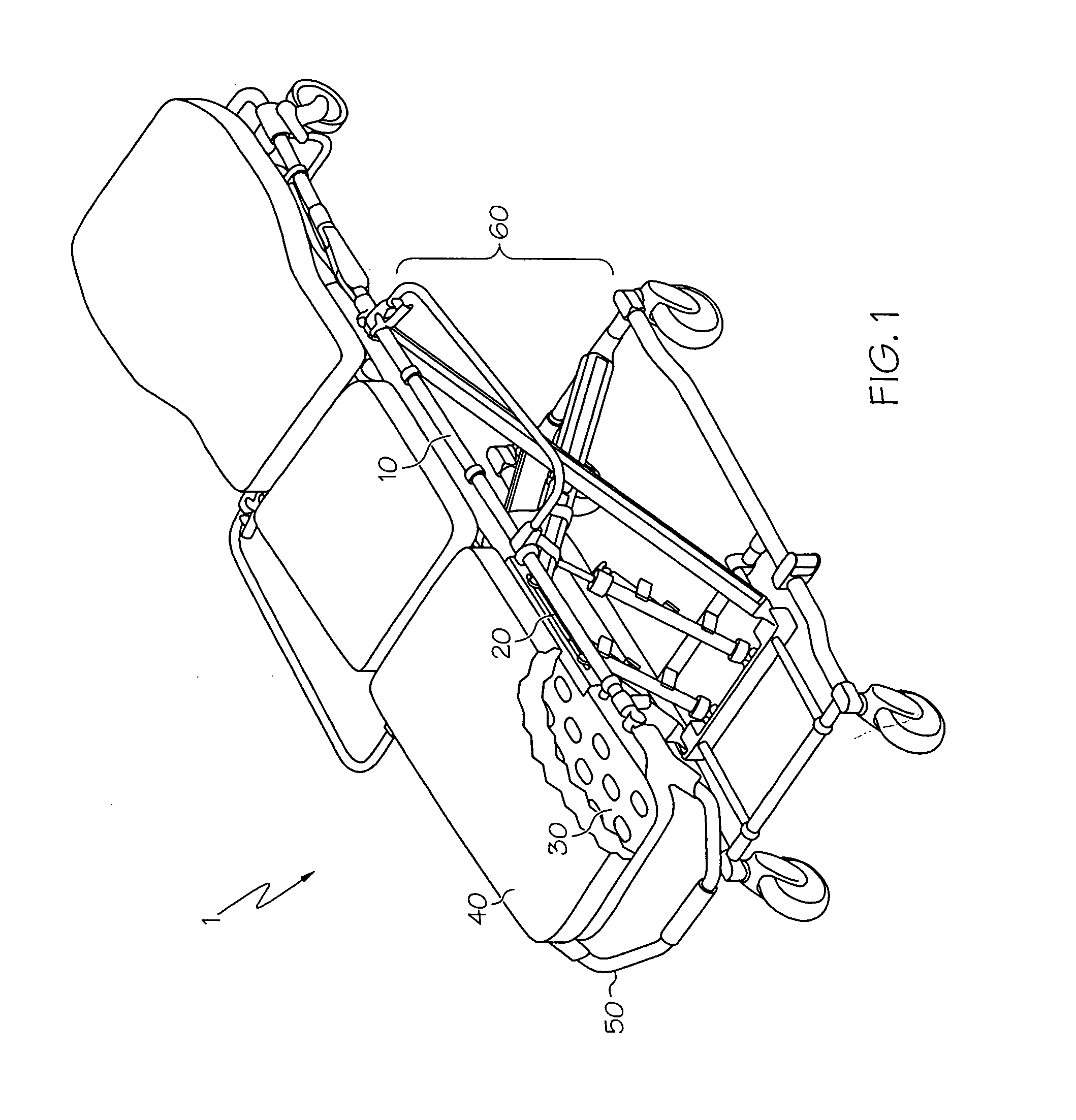
[0014] Referring to FIG. 1, a patient transport cot 1 is provided comprising a height adjustment component coupled to the cot and configured to raise or lower the cot to a plurality of heights. The height adjustment component on the cot may comprise various mechanisms known to one skilled in the art. This may include, but is not limited to, pneumatic mechanisms, hydraulic mechanisms, electronic mechanisms, or the like. In one embodiment as shown in FIG. 1, the cot comprises an unpowered height adjustment component 60 wherein the height of the cot 1 is adjusted by mechanically or mechanically raising or lowering the cot via a lifting bar 50. In a further embodiment, the lifting bar 60 may be utilized for raising or lowering the cot through a ratcheting mechanism. As such mechanisms are known, no further discussion is provided regarding component 60.

[0015] Referring generally to FIGS. 1 and 2, the cot 1 further comprises a mechanical height indicator 20 coupled to the cot 1. A “mecha...


PUM


Abstract

A patient transport cot comprises a height adjustment component coupled to the patient transport cot and configured to raise or lower the cot to a plurality of heights. The patient transport cot further comprises a mechanical height indicator, which comprises at least one height setting, wherein each height setting corresponds to a target cot height. The mechanical height indicator further comprises a moving height marker configured to move with the cot as the cot is raised or lowered, wherein the cot is adjusted to the target cot height when the moving height marker is aligned with the height setting.

Description

FIELD OF THE INVENTION [0001] This invention relates to ambulance cots, and more particularly, ambulance cots comprising height indicators that enable a user to adjust a cot to a specific desired level. BACKGROUND OF THE INVENTION [0002] Manual and electrically powered ambulance cots have greatly improved the loading and unloading as well as the transport of patients. Cots adjust to various heights to facilitate the loading and unloading of patients from hospital beds, ambulances, rescue helicopters, etc. However, this flexibility also creates problems, especially with cots having infinite adjustments within a height range. Operators often find it difficult to quickly adjust a cot repeatedly to a specific desired level, for example, a load height for an emergency vehicle or even a hospital bed. Accordingly, there is a continuing desire to provide ambulance cots and cot components, thereof, which provide greater control and ease of use for an ambulance cot operator. SUMMARY OF THE IN...

Claims


Application Information

Patent Timeline
IPC IPC(8): A61G7/012
CPCA61G1/04A61G1/0567A61G1/0212A61G1/0262A61G7/012
Inventor CHINN, BOB
Owner FERNO WASHINGTON
Learn More