This helps you quickly interpret patents by identifying the three key elements:
Problems solved by technology
Method used
Benefits of technology
Benefits of technology
[0007]According to this method, since the supporting point of the lever engaging with the weight and the master jaw at both ends thereof is at the midpoint, which is the bisected position, a large difference between centrifugal force of the weight and combined centrifugal force of the master jaw and the top jaw is caused, thereby decreasing the gripping force. Namely, difficulty in equalizing a weight of the weight and a weight of the master jaw and the top jaw results in a decrease in the gripping force.
[0015]Therefore, the centrifugal force can be applied effectively without being offset, and weakening of grasping force can be eliminated.
[0022]As described above, according to the chuck of the present invention, since a weight of the weight by the centrifugal force occurring with the rotation of the rotating body is doubled by the lever to be applied to the master jaw side, the weakening of the gripping force is not caused, that is, the centrifugal force on the gripping side can be effectively applied by the centrifugal force of the weight without being offset, thereby eliminating a decrease in gripping force, the chuck can address the fast rotation, and can also prevent an accident from occurring.
[0023]Thus, the stable gripping force of the workpiece can be obtained, and the centrifugal force to the master jaws can be applied in the grasping direction immediately after rotation start of the rotating body by the pressing force in the outer circumferential direction of the rotating body, which has been given to the respective weights.
[0024]Moreover, since the master jaws are drawn in by the fluid applied during machining, and this drawing-in allows the workpiece to be drawn in, the workpiece does not jump out, which enables high-accuracy machining.
[0026]This can make the maintenance taking a lot of time and effort unnecessary and ensure the smooth sliding of the master jaws.
Problems solved by technology
Namely, difficulty in equalizing a weight of the weight and a weight of the master jaw and the top jaw results in a decrease in the gripping force.
When the centrifugal force on the jaw side largely increases by the fast rotation, in the application of cutting force to the workpiece with the machining, not so strong grasping force allows the workpiece to jump out from the gripping portion, which leads to an accident.
Moreover, since there is no drawing-in mechanism for the workpiece, the floating-up of the workpiece occurs together with the gripping force when it is gripped, which makes the chuck unsuitable for high-accuracy machining and fast rotation.
Method used
Image
Click on the blue label to locate the original text in one second.
Reading with bidirectional positioning of images and text.
Examples
first embodiment
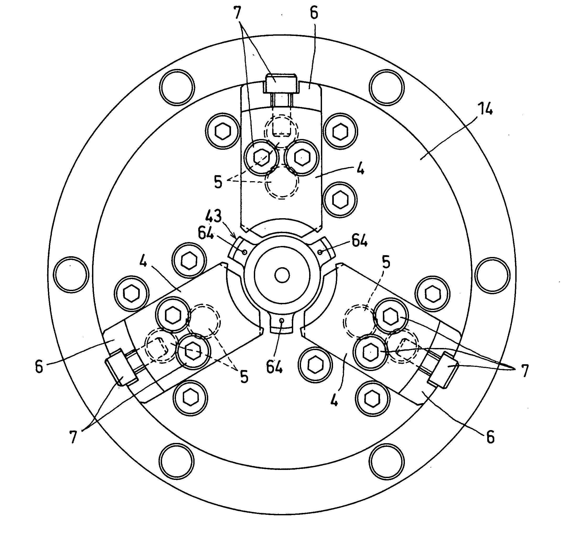
[0036]In the present invention, as shown in FIGS. 1 through 6, there are provided recessed grooves 2 opening a front surface on a plurality of radial lines in the front surface of a rotating body 1 that rotates together with a spindle A of a machine tool, and master jaws 3 each having a gripping claw 4, which slide within a range between grasping and grasping release, are fitted into these respective recessed grooves 2.
[0037]The above-mentioned gripping claw 4 is exchangeably attached through bolts 7 to an attachment seat 6, which is attached to a front surface of the master jaw 3 through bolts 5 in the illustrated case.
[0038]Moreover, behind the master jaw 3 inside of the rotating body 1, a moving-forward and backward unit slid forward and backward by applied fluid pressure.
[0039]With the above-mentioned moving-forward and backward unit S, as shown in FIG. 3, a hollow chamber 8 is provided at the rear of the rotating body 1, and a piston 9 is incorporated in this hollow chamber 8 a...
second embodiment
[0059]According to the present invention, the slide recessed grooves 2 for the master jaws 3 are provided inside of the rotating body 1.
[0060]A reason of the above-described provision of the recessed grooves 2 inside of the rotating body 1 is to prevent the coolant liquid used during machining, cutting debris and the like from entering the inside of the recessed groove 2 to hinder the smooth sliding of the respective master jaws 3, and to require frequent maintenance.
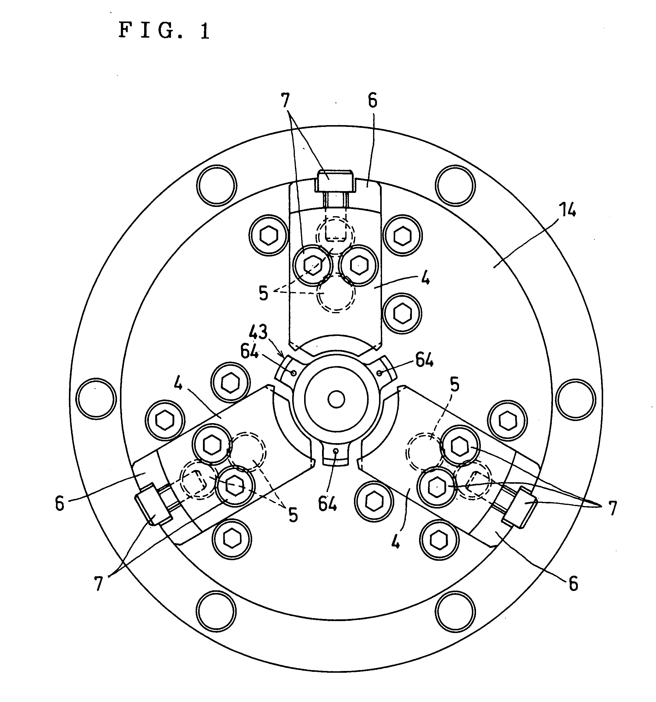
[0061]Therefore, an O ring 51 is interposed in an outer circumference of the front disc 14 fitted into the hollow portion 13 in the front surface of the rotating body 1, and an O ring 52 is interposed in an inner circumference of the disc 14.
[0062]The long hole 20 in the sliding range of each of the master jaws3 is provided in the position of the front disc 14 opposed to each of the master jaws 3, the front portion of the master jaw 3 slidably penetrates this long hole 20, and the gripping claw 4 is attached to the pene...
third embodiment
[0064]According to the present invention, as shown in FIG. 5, protruding force that protrudes the incorporated disc 14 slightly forward is given to the disc 41 by a spring 61.
[0065]The above-mentioned spring 61 is fitted into a recessed portion 67 provided in an opposed surface between a back wall of the hollow portion 13 and the disc 14.
[0066]A collar 62 is fitted into each of the bolts 21 which bind the disc 14 not to rotationally move and are screwed in the disc 14 from the back wall of the hollow portion 13, and a terminal vamplate portion 68 of this collar 62 is fitted into a diameter-expanded recessed step portion 70 having a large diameter on the insertion end side of a penetrating hole 69 for the collar 62, which is provided in the back wall of the hollow portion 13 to limit a protrusion amount of protruding force given by the spring 61 to a certain level and to permit the disc 14 to slide in certain amount of sliding to the back wall side of the hollow portion 13.
PUM
Abstract
An object of the present invention is to prevent the floating-up of a gripped workpiece, and to prevent the gripping from weakening due to centrifugal force accompanying fast rotation. A configuration is employed in which a chuck of the present invention includes master jaws each having a gripping claw and fitted into recessed grooves provided on a plurality of radial lines in a front surface of a rotating body that rotates together with a spindle so as to slide within a range between grasping and grasping release, pistons provided so as to slide forward and backward by fluid pressure applied behind the master jaws inside of the above-mentioned rotating body, an interlocking unit provided so as to slide the above-mentioned master jaws in a grasping direction and in a grasping release direction by the sliding of the pistons, weights incorporated behind the respective master jaws of the above-mentioned rotating body so as to slide in a central direction and in a circumferential direction of the above-mentioned rotating body and is given pressing force in the circumferential direction, and levers each provided so that a distance between an intermediate supporting point and one end engaging with each of the above-mentioned weights is larger than a distance between the intermediate supporting point and another end engaging with each of the above-mentioned master jaws.
Description
BACKGROUND OF THE INVENTION[0001](1) Field of the Invention[0002]The present invention relates to a chuck that prevents a workpiece from floating up by gripping the workpiece, and prevents gripping force to the workpiece from weakening due to centrifugal force acting with fast rotation.[0003](2) Description of the Related Art[0004]A decrease in working accuracy due to floating up in gripping the workpiece causes a defective to occur, and gripping force of the workpiece weakens due to centrifugal force acting on master jaws and top jaws with the fast rotation of a chuck, so that with the weakening gripping force, an adverse effect on the working accuracy is brought about, and the workpiece jumps out due to slip or the like, which causes an accident.[0005]Consequently, there has been a chuck adapted to prevent weakening of the gripping force by the centrifugal force occurring with fast rotation of the chuck (Japanese Examined Utility Model Application Publication No. 56-10483).SUMMARY...
Claims
Application Information
Patent Timeline
Application Date:The date an application was filed.
Publication Date:The date a patent or application was officially published.
First Publication Date:The earliest publication date of a patent with the same application number.
Issue Date:Publication date of the patent grant document.
PCT Entry Date:The Entry date of PCT National Phase.
Estimated Expiry Date:The statutory expiry date of a patent right according to the Patent Law, and it is the longest term of protection that the patent right can achieve without the termination of the patent right due to other reasons(Term extension factor has been taken into account ).
Invalid Date:Actual expiry date is based on effective date or publication date of legal transaction data of invalid patent.

