Disengagement and removal tool for swollen glow plug

Inactive Publication Date: 2010-04-01
ABU ALFARAJ MOHAMMED +1
View PDF4 Cites 3 Cited by
  • Summary
  • Abstract
  • Description
  • Claims
  • Application Information

AI Technical Summary

Benefits of technology

[0002]In view of the above-mentioned disadvantages of the tool which is currently used to disengage and remove the swollen glow plug resulting in wastage of a lot of time and effort in trying to disengage it, th

Problems solved by technology

When the engine runs, the glow plug exposes to high temperature, and with time swells inside the engine.
When the plug is replaced by a new one through the currently used tool, which is a metal fork, the disengagement process becomes difficult firstly because of the glow plug swelling

Method used


Image

  • Disengagement and removal tool for swollen glow plug
  • Disengagement and removal tool for swollen glow plug
  • Disengagement and removal tool for swollen glow plug

Examples


Embodiment Construction

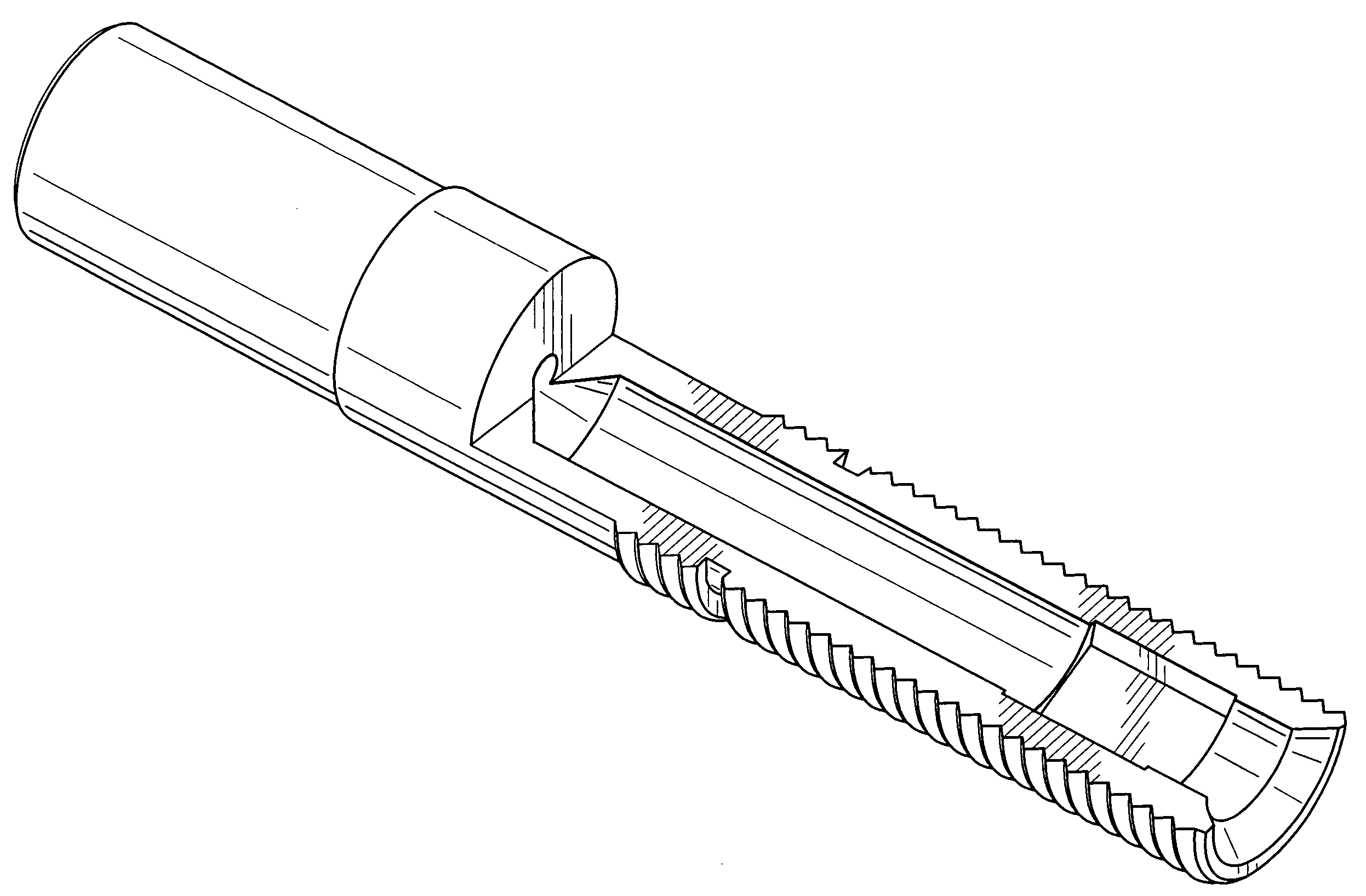
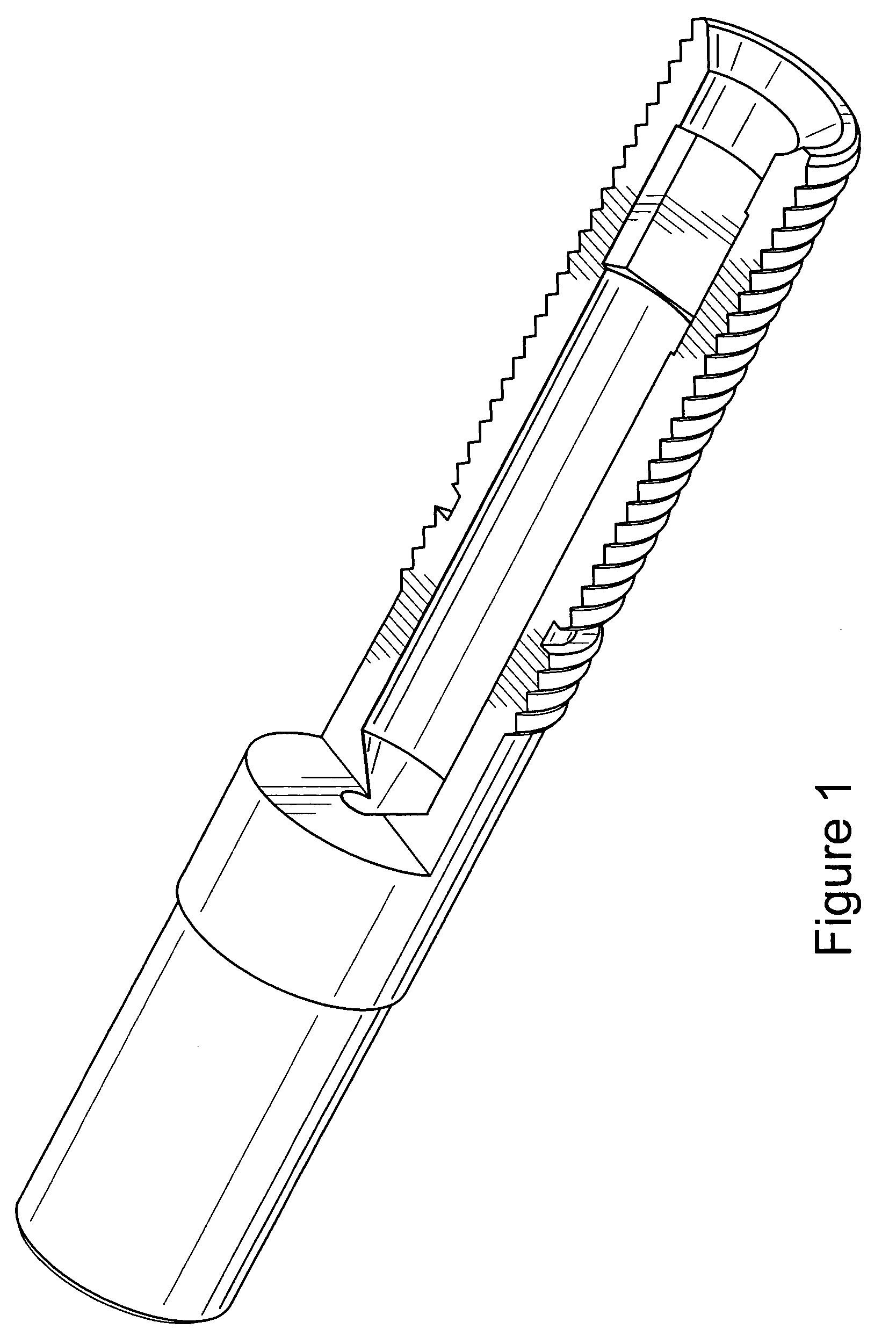
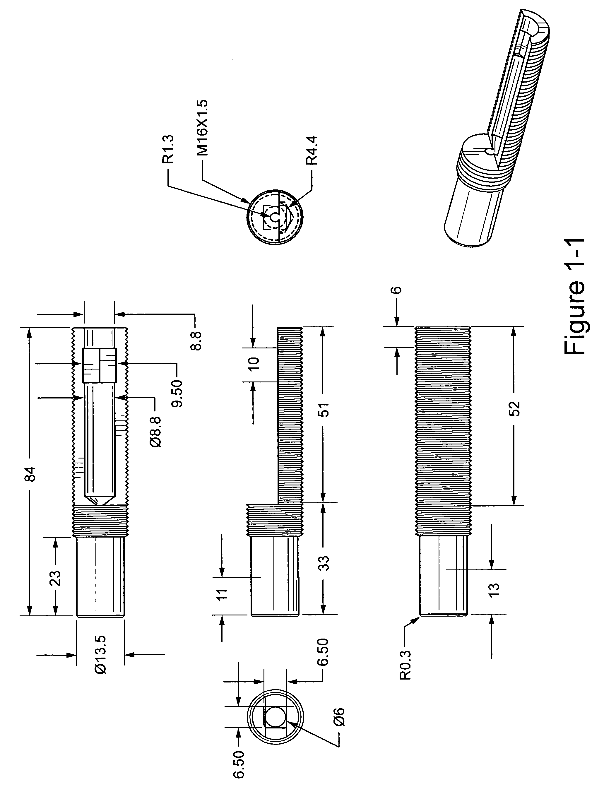
[0013]It will be described in the following and in conjunction with the illustrative drawings shown in FIGS. 1-9 how the new tool carries out the disengagement and removal process for swollen glow plug.

[0014]When the swollen glow plug is disengaged from the engine body, FIG. 4 and FIG. 5 are fastened to form one piece as shown in FIG. 6. Subsequently FIG. 7 is put inside FIG. 6 then FIG. 7 is manually twisted clockwise while stabilizing FIG. 6 until the engine is contacted at the end of twisting process as shown in FIG. 9. Then FIG. 6 is twisted anticlockwise through the automatic switch while stabilizing FIG. 7 with the hook. Thus the swollen glow plug is gradually withdrawn out of the body of the engine in a short time without being exposed to the risk of breakage.


PUM


Abstract

Disengagement and removal tool consists of five metal parts, which can easily remove swollen glow plug without exposure to break and despite the narrow area between the engine and the body of the vehicle. This is done within approximately 60 minutes per vehicle, while the currently used tool takes from one day to one week to do this

Description

BACKGROUND OF THE INVENTION[0001]The field of the invention is related to disengagement and removal tool for swollen glow plugs of diesel engines and hummer vehicles, wherein the plugs are fastened on the engine wall under the atomizer. When the engine runs, the glow plug exposes to high temperature, and with time swells inside the engine. When the plug is replaced by a new one through the currently used tool, which is a metal fork, the disengagement process becomes difficult firstly because of the glow plug swelling and secondly because of the narrow area that does not allow the metal fork to function effectively. Therefore, the disengagement process is time-consuming. Sometimes the swollen plug breaks inside the cylinder when it is removed by the metal fork. In this case it is required that the atomizer should be disengaged to try then to get out the plug through swelling. If this trial is failed, it is required that the head of the engine should be disengaged which means wasting ...

Claims


Application Information

Patent Timeline
IPC IPC(8): B25B13/50
CPCB25B27/02B25B27/0035
Inventor ABU-ALFARAJ, MOHAMMEDAL-TURKY, MOHAMMED ALI
Owner ABU ALFARAJ MOHAMMED
Why Eureka
Try Eureka