Heart valve holder for use in valve implantation procedures

Active Publication Date: 2008-02-07
MEDTRONIC INC
View PDF22 Cites 35 Cited by
  • Summary
  • Abstract
  • Description
  • Claims
  • Application Information

AI Technical Summary

Benefits of technology

[0010]The present invention is directed to a valve holder attached to a bioprosthesis to assist the surgeon in valve implantation. In particular, the valve holder of the invention can be used for aortic valve replacement, and provides for temporary deflection of stent posts of the prosthesis, such as an aortic prosthetic heart valve. This deflection of the stent posts helps to ease the implantation process, and also increases the space available for the surgeon to manipulate the sutures and tie suture knots. The holder of the invention is attached to the tips of the stent posts, which thereby prov

Problems solved by technology

Implantation of a stented prosthetic heart valve presents certain technical challenges.
However, due to a lack of visibility through the prosthetic valve, a surgeon can inadvertently loop sutures around the stent posts during suturing of the annular suture ring portion of the prosthesis.
Similarly, the extending stent posts may undesirably “snag” on chordae or trabeculae inside the left ventricular cavity.
Aortic and pulmonic prosthetic heart valve implantation, however, presents different constraints from those associated with mitral or

Method used


Image

  • Heart valve holder for use in valve implantation procedures
  • Heart valve holder for use in valve implantation procedures
  • Heart valve holder for use in valve implantation procedures

Examples


Example

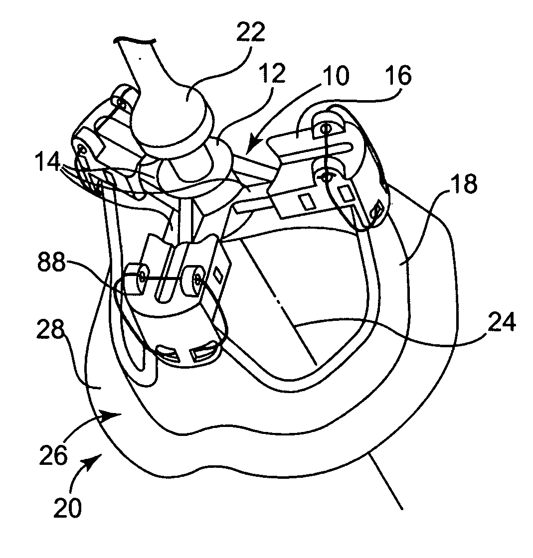
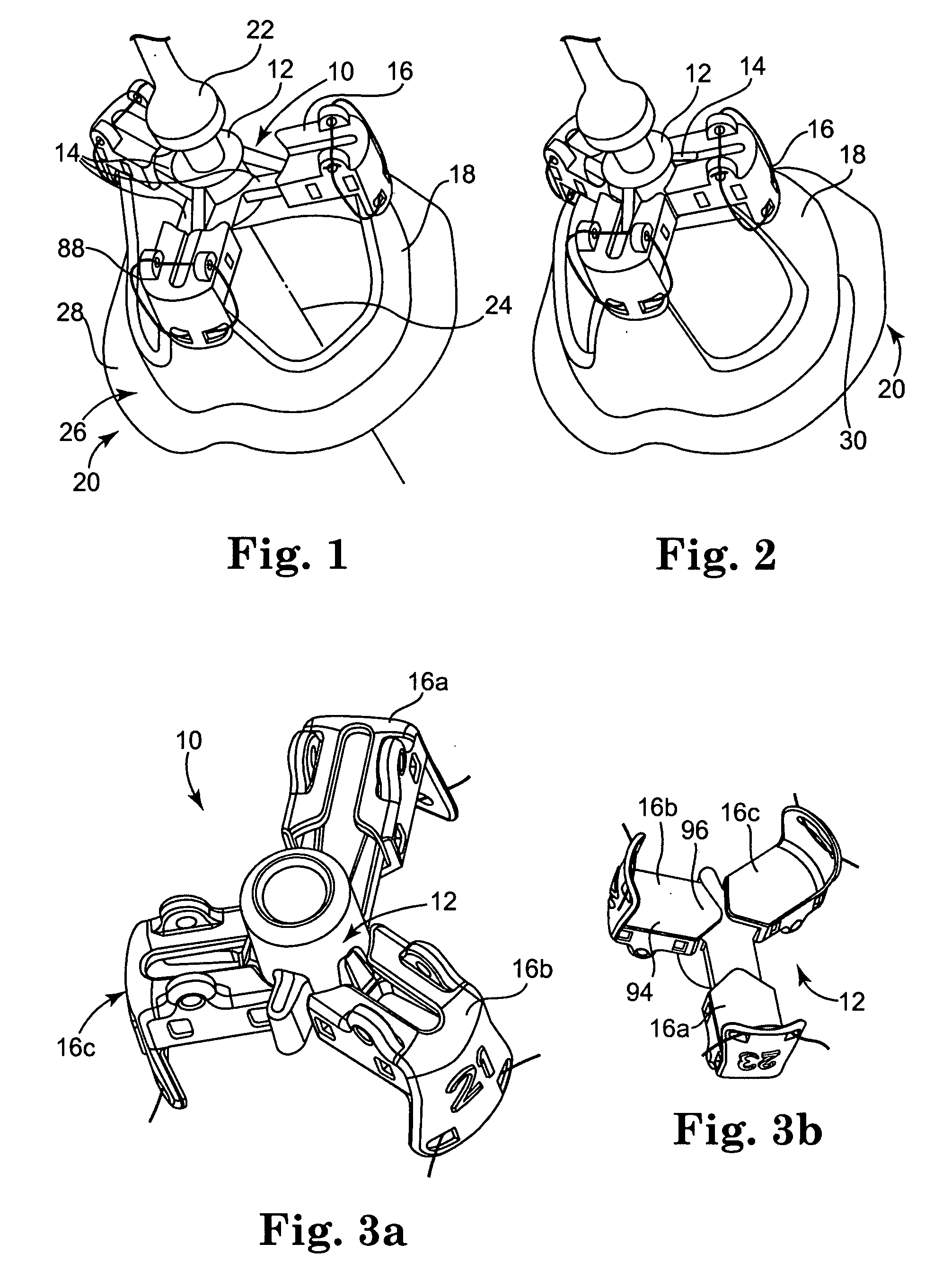
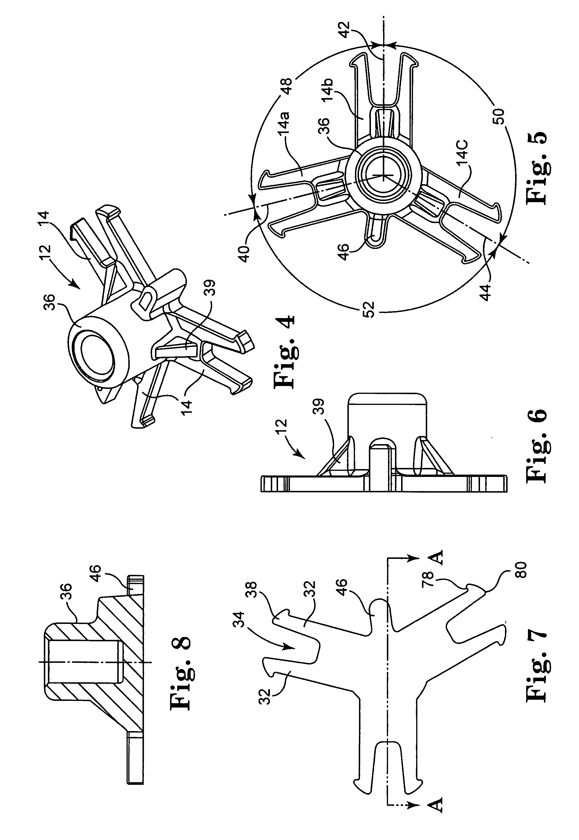
[0032]Referring now to the Figures, wherein the components are labeled with like numerals throughout the several Figures, and initially to FIGS. 1 and 2, a perspective view of one embodiment of a portion of a valve holder 10 of the invention is illustrated. The valve holder 10 generally includes a base member 12 that includes three extending legs 14, and a commissure post engaging member 16 slideably received onto the distal end of each of the extending legs 14. As shown, each of the engaging members 16 is attached to the top of one of three stent posts 18 of a prosthetic heart valve 20, which stent posts 18 are shown in their undeflected condition in FIG. 1 and in their deflected condition in FIG. 2. In general, the engaging members 16 are positioned closer to the center of the base member 12 when the stent posts 18 are deflected (e.g., FIG. 2) than when the stent posts 18 are not deflected (e.g., FIG. 1).

[0033]Valve holder 10 further includes a handle 22 that is attachable to and ...


PUM


Abstract

A valve holder for a prosthetic valve having a stent with a stent base and multiple commissure posts projecting from the stent base, the valve holder including a central base portion, a plurality of legs radially extending from the central base portion, each leg comprising a first prong portion spaced from a second prong portion by a gap distance, a plurality of commissure post engaging members, wherein one commissure post engaging member is slideably engaged with each of the plurality of legs, and a handle extending from the central base portion.

Description

CROSS-REFERENCE TO RELATED APPLICATION[0001]The present application claims priority to U.S. Provisional Application No. 60 / 835,366, filed Aug. 2, 2006, and titled “Heart Valve Holder For Use In Valve Implantation Procedures”, the entire contents of which is incorporated herein by reference in its entirety.TECHNICAL FIELD[0002]The present invention relates generally to implantable valvular prostheses, and more particularly relates to a holding system or mechanism that can provide temporary prosthetic heart valve stent post deflection during implantation of valvular prostheses.BACKGROUND OF THE INVENTION[0003]Various types and configurations of prosthetic heart valves are used to replace diseased natural human heart valves. The actual shape and configuration of any particular prosthetic heart valve is dependent to some extent upon the valve being replaced (i.e., mitral valve, tricuspid valve, aortic valve, and pulmonary valve). In general terms, however, most prosthetic heart valve de...

Claims


Application Information

Patent Timeline
IPC IPC(8): A61F2/24
CPCA61F2/2427
Inventor BERGIN, CATHLEEN A.
Owner MEDTRONIC INC
Why Eureka
Try Eureka