Printhead Carrier For An Imaging Apparatus

a printing head and carrier technology, applied in the field of printing head carriers, can solve the problems of inefficiency, complicated latching process, carrier latches may be oversized,

Active Publication Date: 2008-02-14
FUNAI ELECTRIC CO LTD
View PDF6 Cites 40 Cited by
  • Summary
  • Abstract
  • Description
  • Claims
  • Application Information

AI Technical Summary

Problems solved by technology

However, such carrier latches may involve several moving parts that often complicate the process of latching.
Further, such prior carrier latch...

Method used


Image

  • Printhead Carrier For An Imaging Apparatus
  • Printhead Carrier For An Imaging Apparatus
  • Printhead Carrier For An Imaging Apparatus

Examples


Embodiment Construction

[0021]It is to be understood that the invention is not limited in its application to the details of construction and the arrangement of components set forth in the following description or illustrated in the drawings. The invention is capable of other embodiments and of being practiced or of being carried out in various ways. Also, it is to be understood that the phraseology and terminology used herein is for the purpose of description and should not be regarded as limiting. The use of “including,”“comprising,” or “having” and variations thereof herein is meant to encompass the items listed thereafter and equivalents thereof as well as additional items. Unless limited otherwise, the terms “connected,”“coupled,” and “mounted,” and variations thereof herein are used broadly and encompass direct and indirect connections, couplings, and mountings. In addition, the terms “connected” and “coupled” and variations thereof are not restricted to physical or mechanical connections or couplings...


PUM


Abstract

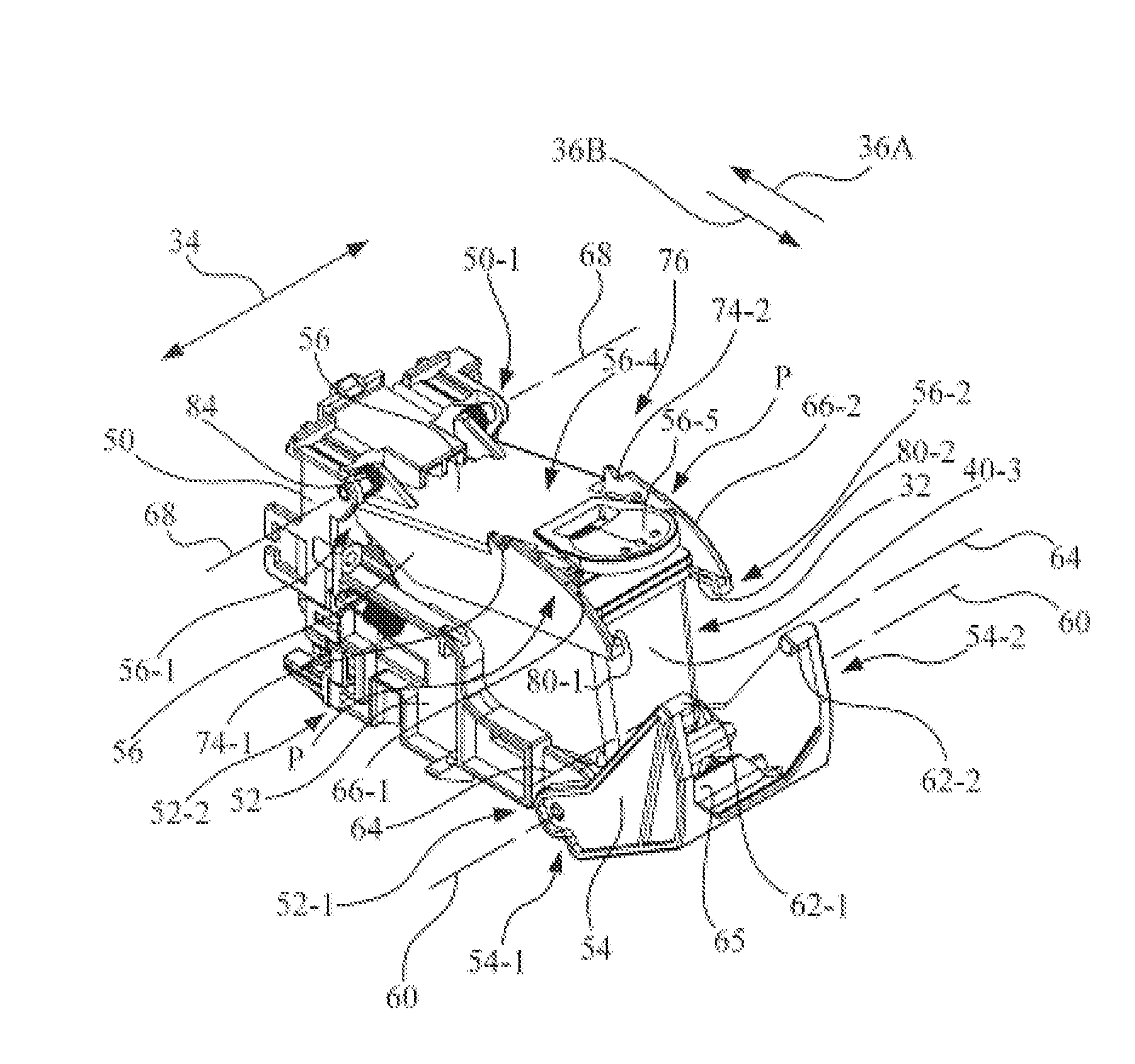
An imaging apparatus includes a printhead carrier for mounting a printhead cartridge. The printhead carrier includes a carrier back wall having an upper portion. A back portion of a printhead cartridge cradle is connected to the carrier back wall. A first proximal end of a latch lever is pivotably attached to a front portion of the printhead cartridge cradle. The latch lever has at least one cam follower, with each cam follower being located near the first distal end of the latch lever. A second proximal end of a carrier lid is pivotably attached to the upper portion of the carrier back wall. Each cam of the carrier lid is formed near a second distal end of the carrier lid, and each cam is positioned for progressive engagement by a corresponding cam follower as the latch lever is moved from an open position toward a latched position.

Description

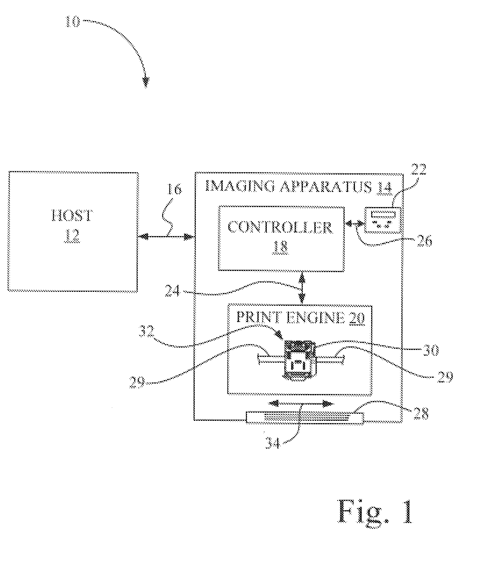
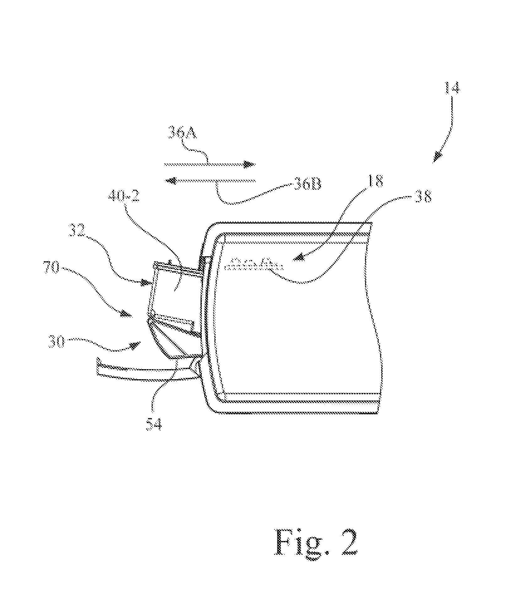
CROSS REFERENCES TO RELATED APPLICATIONS [0001]None.STATEMENT REGARDING FEDERALLY SPONSORED RESEARCH OR DEVELOPMENT[0002]None.REFERENCE TO SEQUENTIAL LISTING, ETC.[0003]None.BACKGROUND[0004]1. Field of the Invention[0005]The present invention relates generally to an imaging apparatus, and more particularly to those having or using a printhead carrier.[0006]2. Description of the Related Art[0007]In the prior art, an imaging apparatus, such as an ink jet printer, forms an image on a print medium, such as paper, by applying ink to the print medium. Such an ink jet printer includes a reciprocating printhead carrier that transports one or more ink jet printhead cartridges across the print medium along a bi-directional scanning path defining a print zone of the printer. An ink jet printhead cartridge, for example, includes both an ink tank containing ink and an ink jet micro-fluid ejection device, i.e., ink jet printhead, for selectively ejecting the ink. Each ink jet printhead cartridge ...

Claims


Application Information

Patent Timeline
IPC IPC(8): B41J2/175B41J2/01
CPCB41J2/1752B41J2/17553B41J2/1755B41J2/17546
Inventor DEVORE, DAVID WAYNEHAWRYSCHUK, TIMOTHY JOHNMURSAY, DAVID KYLESTEWART, STEPHEN EDWARDSTOVES, RANDALL MECLAY
Owner FUNAI ELECTRIC CO LTD
Why Eureka
Try Eureka