Nail clipper with catching side walls

Inactive Publication Date: 2008-03-13
CHA BYUNG KWON
View PDF10 Cites 7 Cited by
  • Summary
  • Abstract
  • Description
  • Claims
  • Application Information

AI Technical Summary

Benefits of technology

[0004]The principal object of the invention is to prevent the nail clippings from jumping away from the clipper and being scattered around the nail clipping site. The purpose of this invention is to block the nail clippings from jumping out of nail clipper so that the clipper user can collect them easily and discard without mess, and it is not intended to store nail clippings inside the clipper for a period of time.
[0005]This invention is a nail clipping device for preventing the nail clippings from jumping away from the clipper and being scattered around the nail clipping site. This device mainly consists of upper elongate part, lower elongate part and lever arm, similar to the most common type of nail clipper in present. Currently the most common type of nail clipper has openings on both sides between upper elongate part and lower elongate part from where the nail clippings jumps out and scatters. This invention includes vertical side walls that are extended from each side edges of upper and lower elongate parts of the clipper. The height of each side wal

Problems solved by technology

The biggest inconvenience of this type of nail clipper is that the clipped part of the nail usually jumps from the clipper and scatter around that bothers the nail cl

Method used


Image

  • Nail clipper with catching side walls
  • Nail clipper with catching side walls
  • Nail clipper with catching side walls

Examples


Embodiment Construction

[0016]For a better understanding of the invention, we turn now to the drawings.

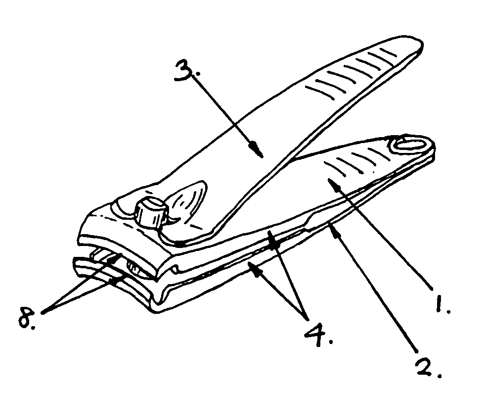
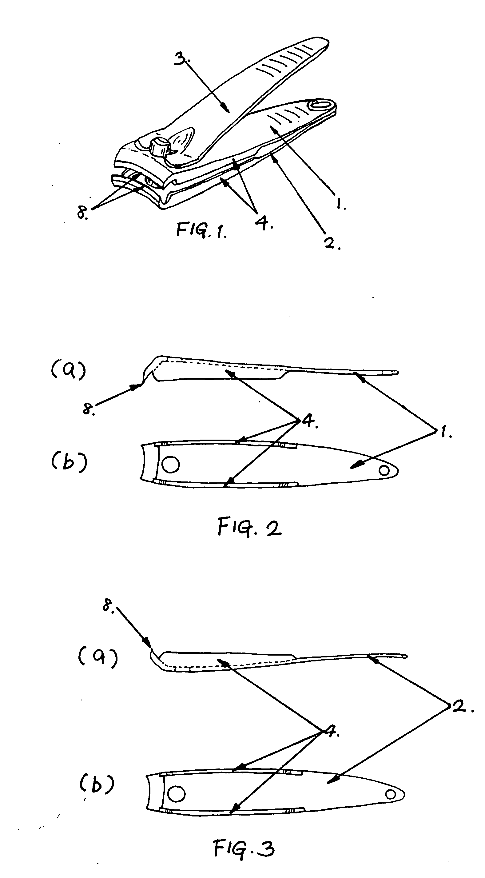
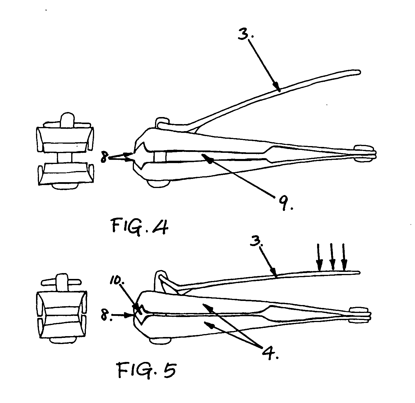
[0017]FIG. 1 offers a visual understanding of how this invention would look like. This nail clipper with catching side walls is mainly consisted of upper elongate part 1, lower elongate part 2, and lever arm 3. Each of upper elongate part 1 and lower elongate part 2 has two of vertical catching side walls 4, one on each side.

[0018]FIG. 2 shows the upper elongate part 1 that has two vertical side walls 4. The vertical side walls are made out of same material as the upper elongate part and it is more like downward extension from the side edges. The height of the vertical side wall 4 is just a little bit shorter than a half of the distance between the upper elongate part 1 and the lower elongate part 2 when the clipper is closed and the upper and lower cutting edges 8 touch each other.

[0019]FIG. 3 shows the lower elongate part that is identical to the upper elongate part. It is just up-side-down shape of the...


PUM


Abstract

A nail clipping device for preventing the nail clippings from jumping away from the clipper and being scattered around the nail clipping site. This device includes vertical catching side walls that are extended from both sides of upper and lower elongate parts of the clipper. The height of each catching side wall is just a little bit shorter than a half of the distance between the upper and lower elongate parts of the clipper when it is closed for cutting. When the clipper is not used the upper and lower catching side walls are apart from each other. However, when it is closed for nail clipping, the catching side walls approximate each other leaving just a small gap between them to form a side barrier to trap the nail clippings within. After clipping nails, by opening the clipper and holding it vertically the clippings can be disposed to desired place. The best point is that this invention does not have complicated structure, and does require minimal or almost no additional cost to manufacture comparing the most common type of nail clipper in current market. And it looks almost identical to the common type of nail clippers except shallow vertical side walls on upper and lower elongate parts that helps people to use this clipper without any hesitation.

Description

FIELD OF THE INVENTION[0001]This invention relates to a device for preventing nail clippings from jumping away and being scattered around during clipping nails.BACKGROUND OF THE INVENTION[0002]Currently most common method to clip nails is by means of nail clipper that comprises two substantially similar, spring like elongate parts, each having a first end forming a transverse cutting edge. And the second ends of the elongate parts are affixed together such that the cutting edges at the first ends are normally spaced apart but can be pressed into cutting engagement against the natural spring bias of the elongate parts. This type of nail clippers has been used for many years because it is easy to use, no maintenance is needed, and it can be manufactured at low cost. The biggest inconvenience of this type of nail clipper is that the clipped part of the nail usually jumps from the clipper and scatter around that bothers the nail clipping person and often others too.[0003]Existing effort...

Claims


Application Information

Patent Timeline
IPC IPC(8): A45D29/00
CPCA45D29/023
Inventor CHA, BYUNG KWON
Owner CHA BYUNG KWON
Why Eureka
Try Eureka