Mirror stabilizer arm connector assembly

a technology for mirror stabilizers and connectors, which is applied in the direction of machine supports, instruments, other domestic objects, etc., can solve the problems of rubber tip that provides friction only a certain amount, wear and loss of friction fit, and loses its fit, so as to prevent uneven wear and premature failure, uniform surface area of engagement

Inactive Publication Date: 2008-04-17
LANG MEKRA NORTH AMERICA LLC
View PDF17 Cites 4 Cited by
  • Summary
  • Abstract
  • Description
  • Claims
  • Application Information

AI Technical Summary

Benefits of technology

[0011] It is a further object of the present invention to provide a connector assembly that accommodates misalignment between t

Problems solved by technology

However, the rubber wears and loses its friction fit.
Since the rubber is not very compressible, the rubber tip that provides the friction can only be compressed a certain amount.
When that rubber insert wears on the friction surface, it loses its fit.
The prior art stabilizer arm connector assembly also has problems in that three parts are utilized that must be fitted together.
To fit the rubber insert properly into the guide block, and then fit the parts into the connector housing, are sometimes

Method used


Image

  • Mirror stabilizer arm connector assembly
  • Mirror stabilizer arm connector assembly
  • Mirror stabilizer arm connector assembly

Examples


Embodiment Construction

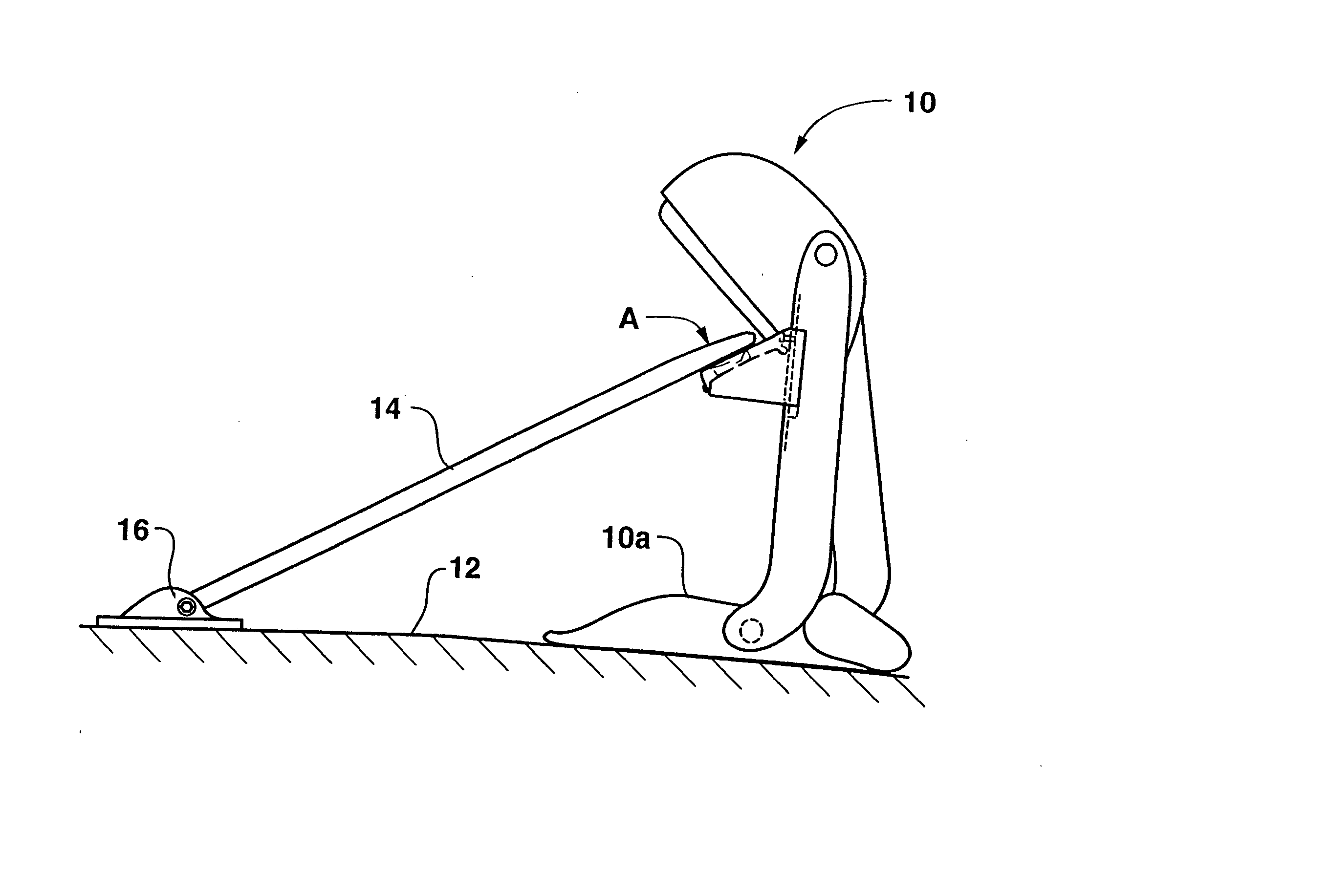
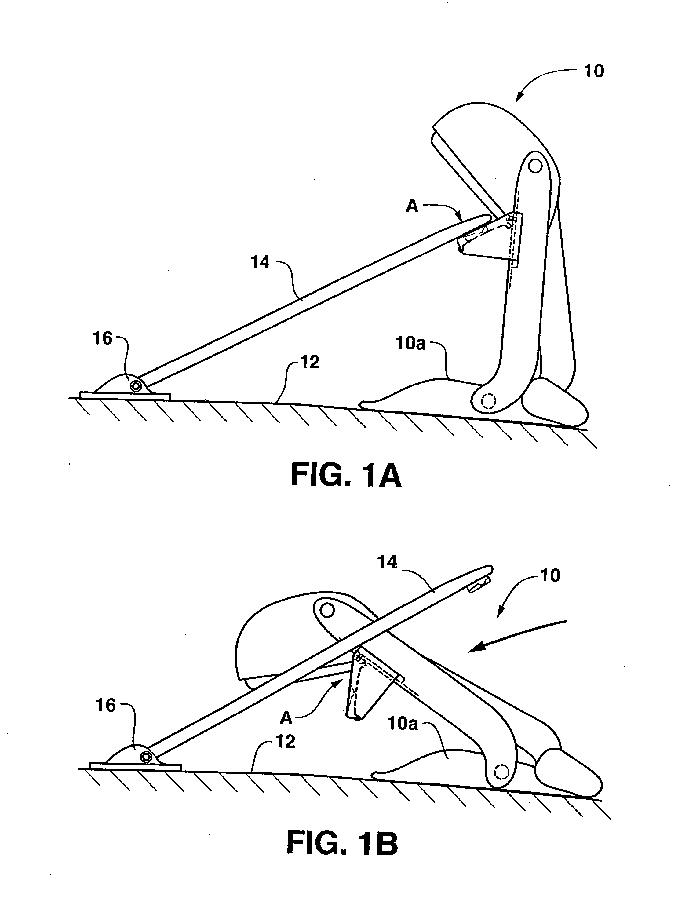
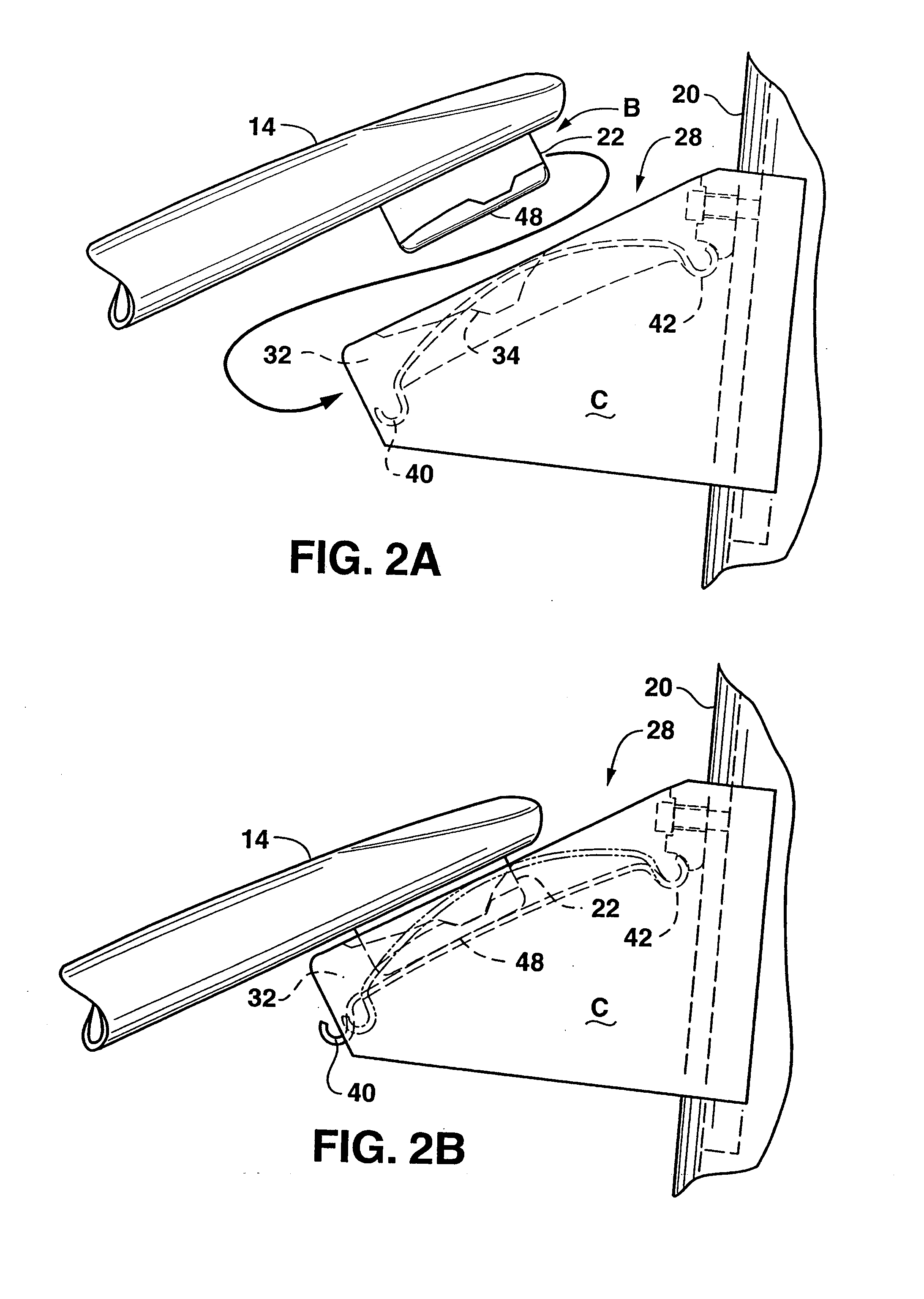
[0043] With reference to the drawings, the invention will now be described in more detail. As can best be seen in FIGS. 1A and 1B, a mirror assembly, designated generally as 10, is illustrated affixed to a body of a vehicle 12. A stabilizer arm 14 is pivotally connected to the vehicle by means of a pivot mount 16. The mirror assembly 10 is connected to the vehicle by suitable fasteners which secure a base 10a to the vehicle 12. Connecting the stabilizer arm to the mirror assembly is a connector assembly, designated generally as A. With the stabilizer arm 14 removed from the connector assembly the mirror assembly may be folded (FIG. 1B). Referring now in more detail to connector assembly A, the connector assembly includes a connector head B and a connector receiver C. While the connector head and receiver may be interchanged on stabilizer arm 14 and a support arm of the mirror assembly, it is preferred that the connector head B be carried by stabilizer arm 14 in that connector receiv...


PUM


Abstract

A connector assembly for releasably attaching a stabilizer arm to a support arm of a vehicle exterior rearview mirror. The assembly includes a connector head carried by the stabilizer arm. The connector head includes a convex bottom surface. A connector receiver is carried by the support arm. A retention slot is included in the connector receiver for receiving the connector head. A first locking element is carried by the connector head. A second locking element is carried within the retention slot for cooperating with the first locking element to releasably engage the connector head with the connector receiver. A biasing element is carried in the retention slot biasing against the convex bottom surface of the connector head for urging the first and second locking elements together, wherein the convex bottom surface pivots on the biasing element to accommodate misalignment between the connector head and the connector receiver.

Description

CROSS REFERENCE TO RELATED APPLICATION [0001] This application is a continuation-in-part of U.S. application Ser. No. 11 / 122,462, filed May 4, 2005.BACKGROUND OF THE INVENTION [0002] 1) Field of the Invention [0003] The invention relates to exterior rearview vehicle mirrors, and more particularly, to a connector assembly that accommodates misalignment when attaching a stabilizer arm to a mirror head support arm. [0004] 2) Description of Related Art [0005] Typically, mirror support assemblies include a C-shape support arm carrying a mirror head which attaches to the vehicle at its free ends. In addition, a stabilizer arm is often used that extends from the vehicle to the support arm to support the mirror head in a more stable manner. Previous stabilizer arms have provided a releasable connection between the stabilizer arm and the support arm. This allows the mirror to be folded for various purposes, and also helps protect the mirror from breaking if it strikes an object. Previous con...

Claims


Application Information

Patent Timeline
IPC IPC(8): G02B7/18
CPCB60R1/0617B60R1/0605
Inventor COURBON, EMMANUELENZ, ANDREAS
Owner LANG MEKRA NORTH AMERICA LLC
Why Eureka
Try Eureka