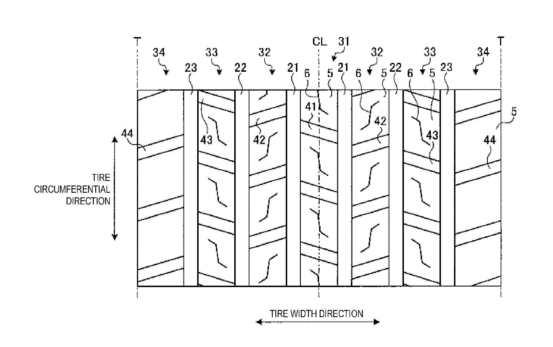
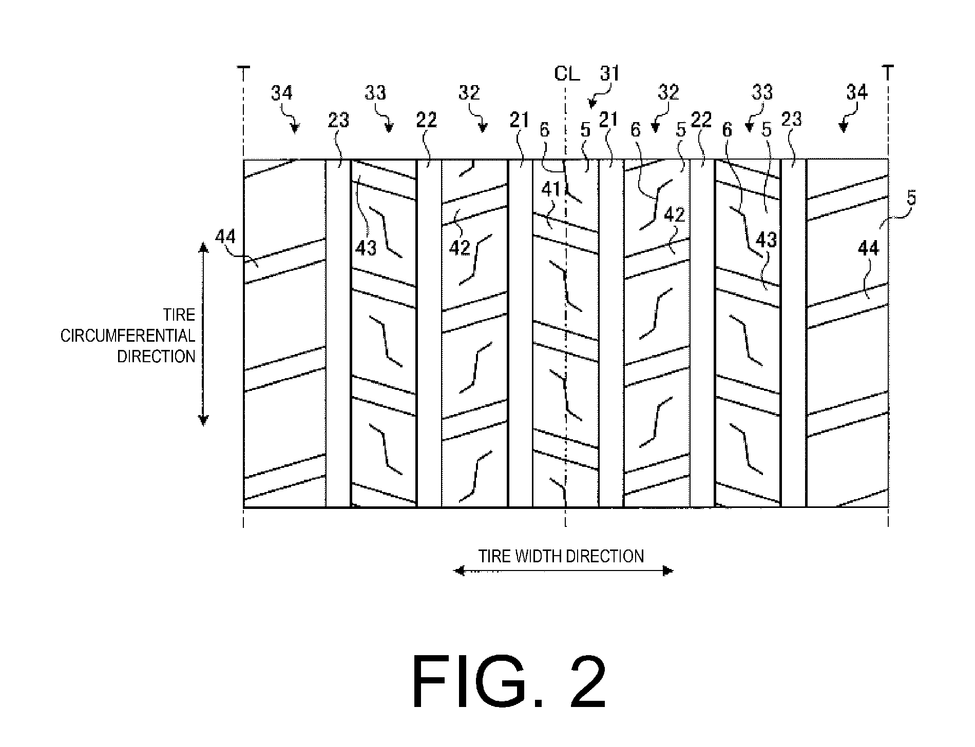
Pneumatic Tire

a pneumatic tire and tire body technology, applied in the field of pneumatic tires, can solve the problems of suppressing the wear of the ribs, and reducing the wear resistance of the tire, so as to improve the uneven wear resistance performance of the tire, enhance the uneven wear resistance of the land portion, and improve the uneven wear resistan

Active Publication Date: 2014-11-06
YOKOHAMA RUBBER CO LTD
View PDF5 Cites 12 Cited by
  • Summary
  • Abstract
  • Description
  • Claims
  • Application Information

AI Technical Summary

Benefits of technology

[0004]The present technology provides a pneumatic tire whereby uneven wear resistance can be enhanced. The pneumatic tire according to the present invention comprises: a belt layer that includes a circumferential reinforcing layer; a plurality of circumferential main grooves; and a plurality of land portions partitioned by the circumferential main grooves. In such a pneumatic tire, the land portions above the circumferential reinforcing layer have at least one sipe, the sipes have a bent shape with two flex points P1, P2 in a plan view, and have a closed structure with two end points Q1, Q2 that terminate within the land portion, an angle α between a line that connects the flex points P1, P2 and the tire circumferential direction is within a range such that 0°≦α≦10°, and an angle β1 between a line that connects the flex point P1 and an end point Q1 and the tire circumferential direction, and an angle β2 between a line that connects the flex point P2 and an end point Q2 and the tire circumferential direction are within a range such that 35°≦1≦55° and 35°≦β2≦55°. In the pneumatic tire according to the present invention, the land portions above the circumferential reinforcing layer have the sipe, so the ground contact pressure of the land portions is reduced, and uneven wear of the land portions (heel and toe wear of blocks, railway wear of the rib) is suppressed. This has the advantage that the uneven wear resistance performance of the tire is improved. Also, the sipe has a bent shape, and the angles of inclination α, β1, and β2 with respect to the tire circumferential direction of the center portion and the end portions thereof are made appropriate, so when turning or when braking / driving, the stress concentrations at the end points Q1, Q2 of the sipe are reduced. As a result, the occurrence of cracking originating at the end points Q1, Q2 of the sipe is suppressed, and this has the advantage that the sipe edge cracking resistance performance of the tire is improved.

Problems solved by technology

On the other hand, in pneumatic tires with a block pattern, there is also the issue that heel and toe wear in the blocks should be suppressed.
Also, in pneumatic tires with a rib pattern, there is the issue that railway wear in the ribs should be suppressed.

Method used


Image

  • Pneumatic Tire
  • Pneumatic Tire
  • Pneumatic Tire

Examples


examples

[0083]FIGS. 8a-8c include a table showing the results of performance testing of pneumatic tires according to embodiments of the present invention.

[0084]In the performance testing, a plurality of mutually differing pneumatic tires were evaluated for (1) uneven wear resistance performance and (2) sipe edge cracking resistance performance (see FIGS. 8a-8c). Also, pneumatic tires with a tire size 445 / 50R22.5 were assembled on a rim having a rim size of 22.5×14.00, and an air pressure of 900 kPa and a load of 4625 kg / tire were applied to these pneumatic tires. Also, the pneumatic tires were mounted on a 6×4 tractor and trailer test vehicle.

[0085](1) In the evaluation of uneven wear resistance performance, a test vehicle was driven on an ordinary paved road for 30,000 km, and thereafter the amount of heel and toe wear of the blocks was measured (the difference in the amount of wear between the area of greatest wear and the area of least wear within a block). Evaluations were performed by ...


PUM

PropertyMeasurementUnit
angleaaaaaaaaaa
angle β2aaaaaaaaaa
length S2aaaaaaaaaa

Abstract

In the pneumatic tire, the blocks above the circumferential reinforcing layer have at least one sipe. Also, the sipe has a bent shape, in a plan view, with two flex points P1, P2, and has a closed structure with two end points Q1, Q2 terminating within the block. Also, the angle α between the line that connects the flex points P1, P2 and the tire circumferential direction is within the range such that 0°≦α≦10°. Also, the angle β1 between the line connecting the flex point P1 and the end point Q1 and the tire circumferential direction, and the angle β2 between the line connecting the flex point P2 and the end point Q2 and the tire circumferential direction are within the range such that 35°≦1≦55° and 35°≦β2≦55°.

Description

TECHNICAL FIELD[0001]The present invention relates to a pneumatic tire, and more specifically, to a pneumatic tire by which uneven wear resistance can be improved.BACKGROUND OF THE INVENTION[0002]In recent years, pneumatic tires have been provided with a circumferential reinforcing layer in a belt layer in order to suppress radial growth of tires and suppress uneven wear (in particular, step wear in a shoulder land portion). The technology described in Japanese Unexamined Patent Application Publication No. 2009-73337A is known as a conventional pneumatic tire that is configured in this manner.[0003]On the other hand, in pneumatic tires with a block pattern, there is also the issue that heel and toe wear in the blocks should be suppressed. Also, in pneumatic tires with a rib pattern, there is the issue that railway wear in the ribs should be suppressed.SUMMARY[0004]The present technology provides a pneumatic tire whereby uneven wear resistance can be enhanced. The pneumatic tire acco...

Claims


Application Information

Patent Timeline
Patent Type & Authority Applications(United States)
IPC IPC(8): B60C11/12B60C9/00
CPCB60C11/1204B60C2011/1213B60C9/0007B60C9/2006B60C9/28B60C11/11B60C11/1263B60C2009/2083B60C2009/2252B60C2009/2257B60C2009/2261B60C2009/2266B60C2011/1254B60C2200/06B60C9/18B60C9/20B60C11/12B60C9/22
Inventor HAMANAKA, HIDEKI
Owner YOKOHAMA RUBBER CO LTD
Why Eureka
Try Eureka