Pneumatic tire

a technology of pneumatic tires and vertices, which is applied in the direction of heavy-duty vehicles, vehicle components, vehicles, etc., can solve the problems of even wear in the vicinities of the side walls of the center blocks of the block side walls

Active Publication Date: 2017-04-20
SUMITOMO RUBBER IND LTD
View PDF9 Cites 2 Cited by
  • Summary
  • Abstract
  • Description
  • Claims
  • Application Information

AI Technical Summary

Benefits of technology

[0006]It is therefore, an object of the present invention to provide a pneumatic tire in which center blocks are improved in the uneven wear resistance.

Problems solved by technology

Accordingly, the sipes disclosed in the patent document 1 tend to cause uneven wear in the vicinities of the vertices of the block side walls of the center blocks.

Method used


Image

  • Pneumatic tire
  • Pneumatic tire
  • Pneumatic tire

Examples


Embodiment Construction

[0059]The present invention can be applied to various kinds of pneumatic tires, but suitably applied to heavy duty tires such as truck / bus tires. Thus, in conjunction with the accompanying drawings, an embodiment of the present invention will now be described in detail, taking a heavy duty as an example.

[0060]As well known in the art, a heavy duty pneumatic tire comprises a tread portion whose outer surface defines the tire tread, a pair of axially spaced head portions mounted on rim seats, a pair of sidewall portions extending between the tread edges and the bead portions, a carcass extending between the bead portions through the tread portion and the sidewall portions, and a tread reinforcing belt disposed radially outside the carcass in the tread portion.

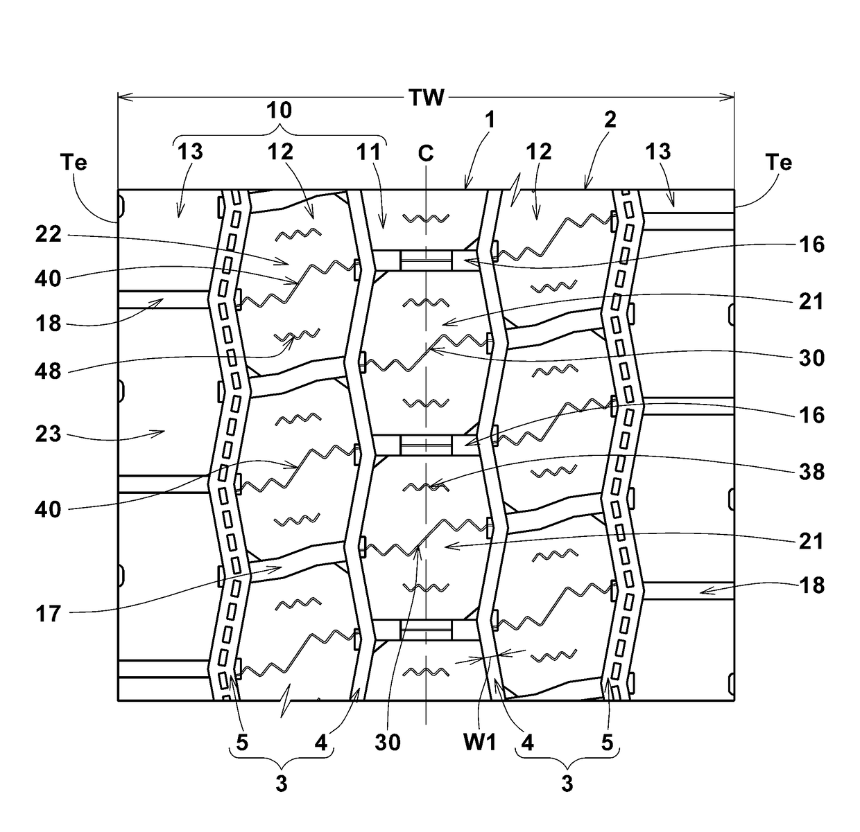
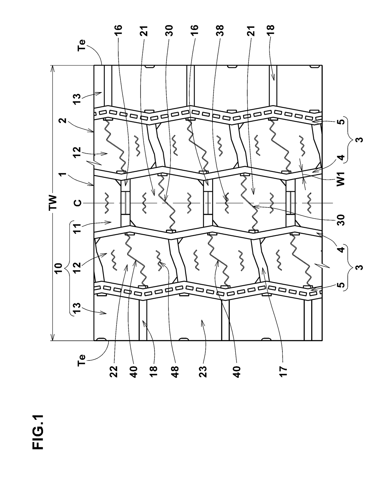
[0061]FIG. 1 shows the tread portion 2 of the tire 1 as an embodiment.

[0062]As shown in FIG. 1, the tread portion 2 is provided with land regions 10 axially divided by main grooves 3 extending continuously in the tire circumferen...


PUM


Abstract

A pneumatic tire comprises a tread portion provided with crown main grooves, center axial grooves and center blocks including a siped center block with a first sipe. The siped center block has a pair of substantially v-shaped opposite first and second block side walls each having an outwardly protruding vertex. The first sipe has a wavy configuration at least partially. One end of the first sipe is positioned on one side in the tire circumferential direction of the vertex of the first block side wall, whereas the other end of the first sipe is positioned on other side in the tire circumferential direction of the vertex of the second block side wall.

Description

TECHNICAL FIELD[0001]The present invention relates to a pneumatic tire whose center blocks disposed in the tread portion are improved in the uneven wear resistance.BACKGROUND ART[0002]For example, the following patent document 1 discloses a pneumatic tire provided with a plurality of center blocks having a hexagonal tread, and the center blocks are provided with sipes extending across the blocks' treads in the tire axial direction. Such sipes can mitigate deformation of the treads when contacting with the ground. Therefore, it is expected the heel and toe wear of the center block is controlled.[0003]In the patent document 1, both ends of the sipe are positioned at vertices of the respective side walls of the block protruding outwardly of the block (vertices of the hexagonal shape of the tread).[0004]In general, the center blocks are subjected to higher ground pressure, therefore, larger stress occurs in the vicinities of the vertices of the block side walls. Accordingly, the sipes d...

Claims


Application Information

Patent Timeline
Patent Type & Authority Applications(United States)
IPC IPC(8): B60C11/12B60C11/03
CPCB60C11/1236B60C11/0304B60C11/0306B60C2011/1213B60C2011/0341B60C2011/0358B60C11/1204B60C11/12B60C2011/1209B60C2011/0346B60C11/11B60C2200/06
Inventor ITO, KAE
Owner SUMITOMO RUBBER IND LTD
Why Eureka
Try Eureka