Pneumatic Tire

a pneumatic tire and tread technology, applied in the field of pneumatic tires, can solve the problems of reduced rigidity of the tread portion, decreased drainage performance, and decreased steering stability on dry road surfaces, and achieve the effects of ensuring steering stability, good steering stability, and ensuring the rigidity of the land portion

Active Publication Date: 2019-01-31
THE YOKOHAMA RUBBER CO LTD
View PDF4 Cites 2 Cited by
  • Summary
  • Abstract
  • Description
  • Claims
  • Application Information

AI Technical Summary

Benefits of technology

[0007]In the present technology, the center main groove extending in the tire circumferential direction and the shoulder main groove extending in the tire circumferential direction on the outside of the center main groove formed in the tread portion and the plurality of lug grooves formed in the land portion defined between the center main groove and the shoulder main groove ensure steering stability on wet road surfaces. Moreover, the lug grooves terminating within the land portion sufficiently ensure the rigidity of the land portion while providing good steering stability on dry road surfaces and that on wet road surfaces in a compatible manner. Furthermore, the bent portion formed in the lug groove extending inward in the tire lateral direction from the shoulder main groove can increase the effect of enhancing wet performance through the edge effect of the bent portions. Additionally, the raised bottom portion in the bend portion, for creating a level difference with respect to the lug grooves and being shallower than the lug grooves, prevent a local decrease in rigidity of the land portion, resulting in enhancement of steering stability on dry road surfaces and uneven wear resistance. In this way, good steering stability on dry road surfaces and wet road surfaces, which are in a negative correlation, are achieved in a compatible manner, and furthermore, uneven wear resistance is improved at the same time.
[0008]In the present technology, a depth Dx of the bent portion at the raised bottom portion and a depth Dr of the lug groove preferably satisfy a relationship of 0.10×Dr≤Dx≤0.70×Dr. Setting the depth Dx of the bent portion at the raised bottom portion in the above-described range effectively enhances steering stability on dry road surfaces and uneven wear resistance while reliably ensuring the effect of enhancing wet performance.
[0009]Additionally, the center main groove preferably has a zigzag shape extending in the tire circumferential direction, a plurality of narrow grooves preferably intermittently extend in the tire circumferential direction in the land portion without communicating with the bent portion, and the narrow grooves are preferably substantially parallel with the center main groove having the zigzag shape. The center main groove having the zigzag shape and the narrow grooves intermittently disposed to be substantially parallel with the center main groove provide good steering stability on dry road surfaces and wet road surfaces in a highly compatible manner, and can further enhance uneven wear resistance.
[0010]Additionally, a depth Ds of the narrow grooves and a depth Dc of the center main groove having the zigzag shape preferably satisfy a relationship of 0.10×Dc≤Ds≤0.50×Dc. Setting the depth Ds of the narrow grooves in the above-described range effectively enhances steering stability on dry road surfaces and uneven wear resistance.
[0011]Furthermore, a gap d1 between the narrow grooves and the center main groove having the zigzag shape in a tire axial direction and a width d2 of the land portion in the tire axial direction preferably satisfy a relationship of 0.10×d2≤d1≤0.40×d2. Setting the gap d1 between the narrow grooves and the center main groove having the zigzag shape in the above-described range maximizes the effect of enhancing uneven wear resistance.
[0012]Furthermore, an inclination angle α of the lug grooves each having the bent portion with respect to the tire circumferential direction is preferably within a range of from 25° to 75°. Setting the inclination angle α of the lug grooves with respect to the tire circumferential direction in the above-described range reliably ensures the effect of enhancing steering stability on dry road surfaces.

Problems solved by technology

However, when the number of lug grooves in the tread portion increases, the rigidity of the tread portion decreases, and thus steering stability on dry road surfaces declines.
On the other hand, when the number of lug grooves in the tread portion decreases, the drainage performance decreases, and thus steering stability on wet road surfaces declines.
In this manner, the steering stability on dry road surfaces and the steering stability on wet road surfaces are in a negative correlation, and, consequently, it is difficult to improve both the steering stability on dry road surfaces and the steering stability on wet road surfaces at the same time.
Additionally, when the tread portion is subdivided by the main grooves and the lug grooves, the rigidity of the tread portion is made nonuniform, causing uneven wear in the tread portion readily.
Since there are some restrictions on the layout of the main grooves and the lug grooves to suppress uneven wear, it is more difficult to improve uneven wear resistance while achieving good steering stability on dry road surfaces and wet road surfaces in a compatible manner.

Method used


Image

  • Pneumatic Tire
  • Pneumatic Tire
  • Pneumatic Tire

Examples


Embodiment Construction

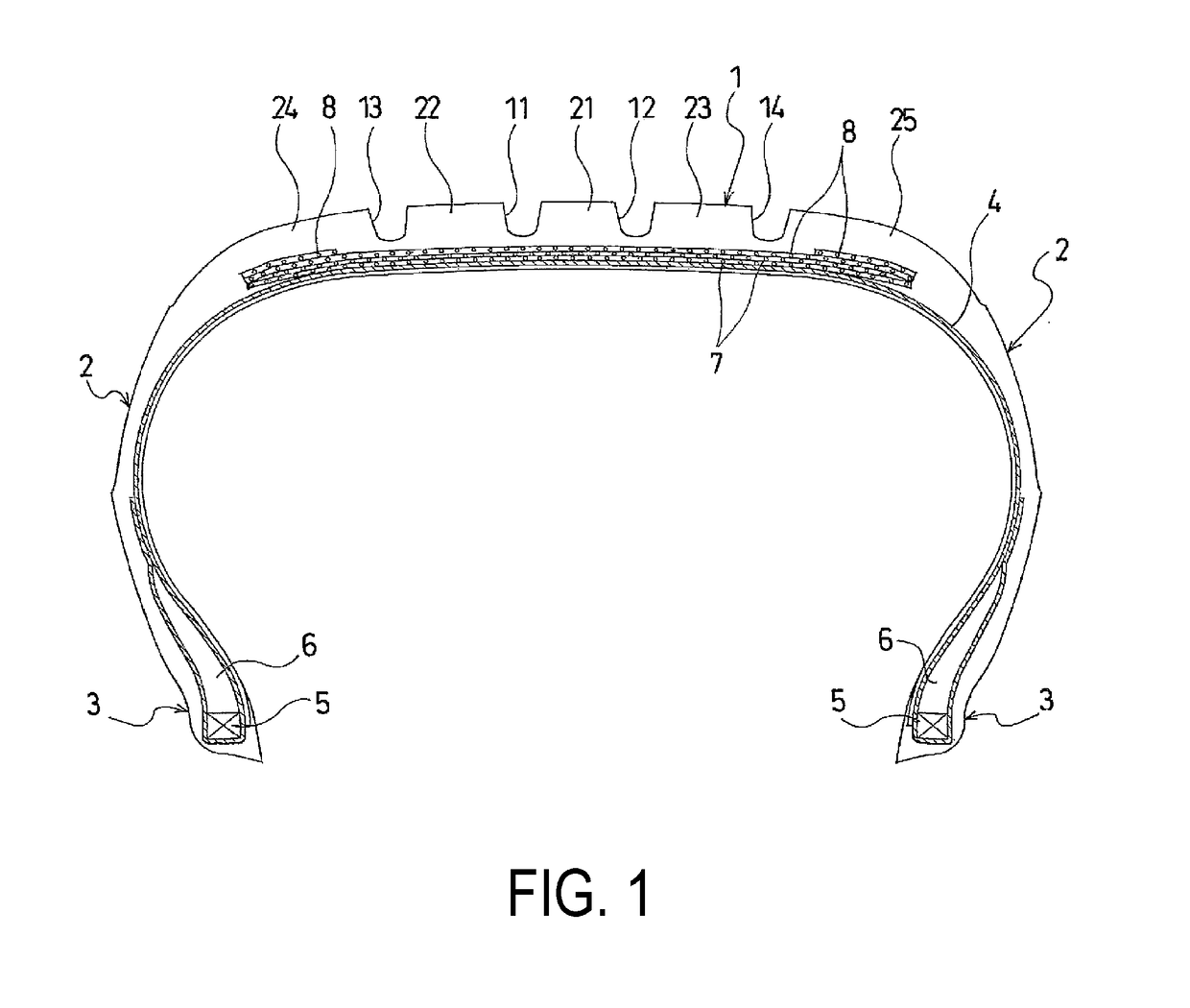
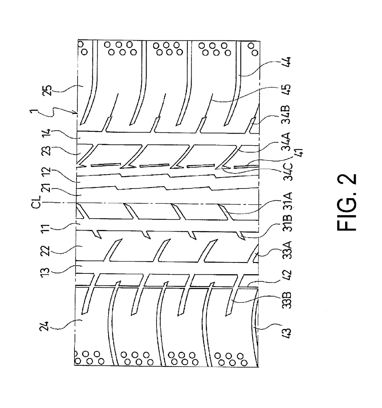
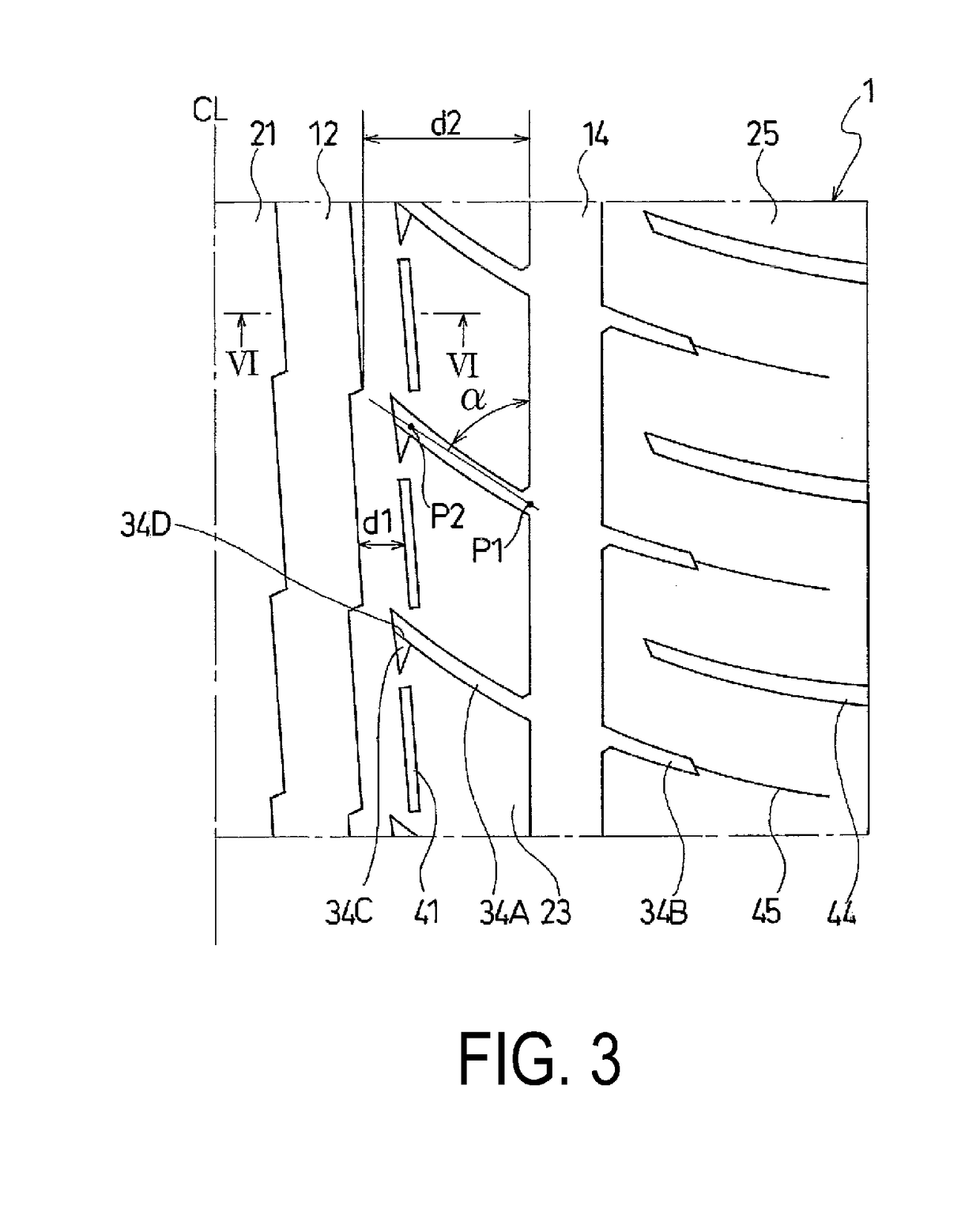
[0019]The configuration of the present technology is described in detail below with reference to the accompanying drawings. FIGS. 1 to 6 illustrate a pneumatic tire according to an embodiment of the present technology.

[0020]As illustrated in FIG. 1, a pneumatic tire of the present embodiment includes an annular tread portion 1 extending in the tire circumferential direction, a pair of sidewall portions 2, 2 disposed on both sides of the tread portion 1, and a pair of bead portions 3, 3 disposed inward of the sidewall portions 2 in the tire radial direction.

[0021]A carcass layer 4 is mounted between the pair of bead portions 3, 3. The carcass layer 4 includes a plurality of reinforcing cords extending in the tire radial direction and is folded back around bead cores 5 disposed in each of the bead portions 3 from a tire inner side to a tire outer side. A bead filler 6 having a triangular cross-sectional shape formed from rubber composition is disposed on a periphery of the bead core 5...


PUM


Abstract

A pneumatic tire is provided, the pneumatic tire including a tread portion, sidewall portions, and bead portions, and the pneumatic tire includes, in the tread portion, a center main groove extending in a tire circumferential direction and a shoulder main groove extending in the tire circumferential direction on the outside of the center main groove; a land portion between the main grooves; lug grooves extending inward in a tire lateral direction from the shoulder main groove and terminating without communicating with the center main groove; a bent portion bending toward one side in the tire circumferential direction, at a terminating end of each of the lug grooves; and a raised bottom portion included in the bent portion, creating a level difference with respect to a lug groove, and being shallower than the lug groove.

Description

TECHNICAL FIELD[0001]The present technology relates to pneumatic tires including center main grooves extending in a tire circumferential direction, shoulder main grooves extending in the tire circumferential direction on the outside of the center main grooves, and land portions extending in the tire circumferential direction between the center main grooves and the shoulder main grooves in tread portions, and more specifically, relates to pneumatic tires that have improved uneven wear resistance while achieving good steering stability on dry road surfaces and wet road surfaces, which are in a negative correlation, in a compatible manner by appropriately setting configurations of tread patterns.BACKGROUND ART[0002]Pneumatic tires use a tread pattern in which a plurality of main grooves extending in a tire circumferential direction and rows of land portions defined by the main grooves are formed in a tread portion (for example, see Japanese Unexamined Patent Publication No. 2012-228992...

Claims


Application Information

Patent Timeline
Patent Type & Authority Applications(United States)
IPC IPC(8): B60C11/04
CPCB60C11/042B60C11/13B60C11/0302B60C11/01B60C11/1204B60C2011/0346B60C2011/0348B60C2011/0351B60C2011/1213B60C11/0304B60C2011/0388B60C11/032B60C2011/0341B60C11/1376B60C2011/0381B60C2011/0372
Inventor SHIBAI, TAKASHI
Owner THE YOKOHAMA RUBBER CO LTD
Why Eureka
Try Eureka